Create an interactive liquid metal ball with WebGL
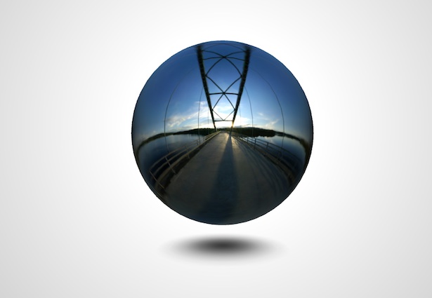
So you want to create an interactive WebGL liquid metal ball? Glad you asked, programming wizard Paul Lewis has got just the thing!
Daily design news, reviews, how-tos and more, as picked by the editors.
You are now subscribed
Your newsletter sign-up was successful
Want to add more newsletters?

Five times a week
CreativeBloq
Your daily dose of creative inspiration: unmissable art, design and tech news, reviews, expert commentary and buying advice.

Once a week
By Design
The design newsletter from Creative Bloq, bringing you the latest news and inspiration from the worlds of graphic design, branding, typography and more.

Once a week
State of the Art
Our digital art newsletter is your go-to source for the latest news, trends, and inspiration from the worlds of art, illustration, 3D modelling, game design, animation, and beyond.

Seasonal (around events)
Brand Impact Awards
Make an impression. Sign up to learn more about this prestigious award scheme, which celebrates the best of branding.
Making websites is tons of fun, but sometimes you need to break free and do something a bit unusual. That’s what we’ll be doing today. We’ll be using the excellent Three.js engine to create an interactive metallic ball. As you click and drag the ball distorts and then slowly settles back to its original shape.
To do this we’ll be covering spring physics, 3D vectors and ray casting (and a few other things besides) all in an effort to create a compelling and fun interactive experience. Let’s start by looking at what we’re going to make.
The thing about experiments like these is that on the surface they don’t look to have direct commercial applications. You’d be forgiven for thinking the same about this one as well, and perhaps you’re right. But my philosophy is that as a developer you learn techniques and solutions to problems in these experiments that can help you in your day-to-day work. There have been many times where this has proved true for me, and I’m certain it’ll work out for you as well. In any case this is going to be tons of fun, so let’s get started on creating our scene.
Setting up
To get started we’re going to need to create a scene, a camera and a renderer:
/** * Creates the 3D scene, camera and WebGL renderer. * Then goes ahead and adds the renderer to the body */function init() { var width = window.innerWidth, height = window.innerHeight, ratio = width / height; // set up the scene and camera scene = new THREE.Scene(); camera = new THREE.PerspectiveCamera( 75, // camera angle, ratio, // viewport ratio 1, // near plane, and far plane below 10000); // create a renderer with antialiasing on renderer = new THREE.WebGLRenderer({ antialias: true }); renderer.setSize(width, height); // now add the camera to the scene // and the WebGL context to the DOM scene.add(camera); document.body.appendChild(renderer.domElement); // do everything else createObjects(); createSprings(); bindCallbacks(); displaceRandomFace(); requestAnimationFrame(animate);}If you want a more in-depth guide to getting started with Three.js you can find that on my site.
I’ll assume that you’ve got your scene up and running. Now if you were to view this, you’d see absolutely nothing, which is a touch depressing, so let’s put something in there!
Creating the sphere and floor
In our scene we have two objects, the ball (a sphere) and the shadow on the floor. The sphere is a standard Three.js primitive (which I’ve modified slightly, but more on that later!) and the floor is a plane textured with a gradient to look like shadow. Real-time shadows are really awesome, but for this tutorial our image will give us a good look.
Daily design news, reviews, how-tos and more, as picked by the editors.
Creating the sphere involves creating the geometry (the vertices and faces) and then creating a material so that it looks like it’s metallic.
To create the geometry we use the following code:
// create the sphere geometrysphereGeometry = new THREE.SphereGeometry( 200, // radius 60, // resolution x 30); // resolution yPretty straight forward, I hope! We have vertices, what about our material? Well, this is slightly more involved. Now we need to load in a texture cube (or a cube map as it’s sometimes called) to give us the reflections, and we need to create a material that uses this cube map:
// first create the environment mapvar urls = [ 'envmap/posx.jpg', 'envmap/negx.jpg', 'envmap/posy.jpg', 'envmap/negy.jpg', 'envmap/posz.jpg', 'envmap/negz.jpg'],// wrap it up into the object that we needtextureCube = THREE.ImageUtils.loadTextureCube(urls);// create the sphere's materialsphereMaterial = new THREE.MeshLambertMaterial({ color : 0xEEEEEE, envMap : textureCube, shininess : 200, shading : THREE.SmoothShading});// now create the sphere and then// declare its geometry to be dynamic// so we can update it later onsphere = new THREE.Mesh(sphereGeometry, sphereMaterial);sphere.geometry.dynamic = true;So you can see that we start by creating the environment map, or TextureCube. In my case I’m using one of the environment maps that comes with Three.js, but you could use another. We then create a texture cube and apply it to the material’s envMap, or environment map. This means that the sphere will reflect the cube’s texture. You will also see that we give the sphere a colour. This colour is multiplied by the texture on the cube and that’s the final colour we see. So, for example, black will give us no reflection and white will give us a full reflection. Here I’ve chosen a light grey. The last thing to mention on the sphere is that we’ve declared the geometry to be dynamic:
sphere.geometry.dynamic = true;All this really means is that we’re telling Three.js that at some point we’re going to be updating the vertices and faces and that it needs to keep that information around. If we don’t it’ll merrily remove the geometry data, which is normally a good thing as it keeps memory usage down.
Let’s move on to the floor. This is actually pretty simple, so let’s dive straight into that code:
// create the floorplaneGeometry = new THREE.PlaneGeometry( 400, 400, 1 );planeMaterial = new THREE.MeshBasicMaterial({ color: 0xFFFFFF, map: THREE.ImageUtils.loadTexture("floor.png"), transparent: true});plane = new THREE.Mesh(planeGeometry, planeMaterial);This time we create a PlaneGeometry with a width and height of 400 and a texture of a gradient which looks a little like this:

Finally we need to rotate the floor and position it below the sphere:
// position the floor down a little// and rotate it to be perpendicular// to the centre of the sphereplane.rotation.x = Math.PI * -0.5;plane.position.y = -150;Great! So now if you open the scene up it should look a little like this:

Ray intersection
This is where things start to get really fun. What we want to do now is have the ball react to mouse clicks. As we click and drag the surface of the ball should distort, then it should settle down in a fluid manner. Let’s deal with the first part, the distortion.
To get to our solution we first need to understand ray casting, which may sound a little daunting, but I assure you it’s not. Whenever we draw a 3D shape on screen we are actually drawing it in 2D. Your screen, after all, is a 2D box. This process is called projecting and is very much like in real life where you might project an image on a wall. This also gives us a problem, because when you click on the scene we know the x and y coordinates of where you clicked but what we don’t know is the z coordinate; we don’t know how far into the screen you were meaning to click.
To fix this we take the x and y coordinates of where you clicked and we create an infinitely long line, or ray, inside our 3D scene which, when flattened again (like the rest of our scene), would give us that click’s x and y coordinate. In effect, then, our ray represents all the possible 3D locations that could represent the clicked location. This process is called unprojecting. What we can then do with this is create a ray starting at our camera’s position with our unprojected line and see if it intersects our sphere at any point. If it does intersect, we’ll find out exactly where and distort the faces of the sphere right at that location.
As is typical with Three.js there are handy functions we can use to do this:
/** * Checks to see if the mouse click implies * a ray intersection with the sphere and, if * so, goes about displacing the face that it hit * * @param {Event} evt The mouse event */function checkIntersection(evt) { // get the mouse position and create // a projector for the ray var mouseX = evt.offsetX || evt.clientX, mouseY = evt.offsetY || evt.clientY, projector = new THREE.Projector(); // set up a new vector in the correct // coordinates system var vector = new THREE.Vector3( (mouseX / window.innerWidth) * 2 - 1, -(mouseY / window.innerHeight) * 2 + 1, 0.5); // now "unproject" the point on the screen // back into the the scene itself. This gives // us a ray direction projector.unprojectVector(vector, camera); // create a ray from our current camera position // with that ray direction and see if it hits the sphere var ray = new THREE.Ray(camera.position, vector.subSelf(camera.position).normalize()), intersects = ray.intersectObject(sphere); // if the ray intersects with the // surface work out where and distort the face if(intersects.length) { displaceFace(intersects[0].face, DISPLACEMENT); }}The actual process of ray creation in Three.js is done by taking the camera’s position and the direction that our virtual unprojected ray has. The direction is a normalised vector (a vector whose length is 1) of the 3D line between our unprojected mouse click coordinates and the camera’s position.
Finally you’ll see that if Three.js reports an intersection that we distort the face that it’s told us has been hit. For simplicity we only care about the first intersection it finds. There’ll likely be a second intersection on the other side of the sphere where our ray shoots out the other side.
Spring physics
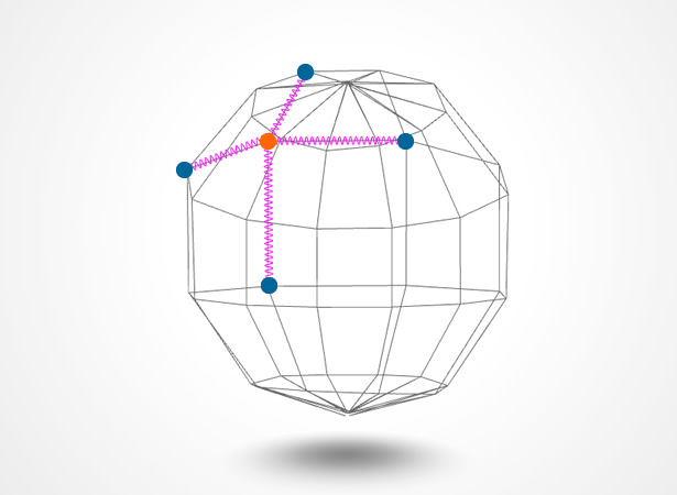
Now we’re catching the clicks and distort our faces we have to make our sphere settle down in a fluid manner. To do this we’ll be using a basic spring setup. Since a picture tells a thousand words let’s have a look at one:

What we’ll be doing is creating a spring between each of the vertices that make up the sphere. In the picture above I’ve simplified the sphere model to make it clearer. I’ve highlighted one of the vertices in orange, the virtual springs in glorious hot pink and the vertices to which our orange one is connected in blue. Now when we distort the sphere we’ll code it so those springs try and return to their starting position, all through the wonder of Hooke’s Law.
The first thing we’ll do is go through each face and, for each one, we will create springs between its constituent vertices:
/** * Creates an individual spring * * @param {Number} start The index of the vertex for the spring's start * @param {Number} end The index of the vertex for the spring's start */function createSpring(start, end) { var sphereVertices = sphere.geometry.vertices; var startVertex = sphereVertices[start]; var endVertex = sphereVertices[end]; // create a spring startVertex.springs.push({ start : startVertex, end : endVertex, length : startVertex.position.length( endVertex.position ) });}To make things a bit simpler I’ve removed the code that creates the spring array inside each vertex, but if you take a look at the sample code provided you’ll see it in all its glory. You can see that we’re creating a spring with references to each vertex’s position and the original length of the spring. Having the length will let us see how far it has extended and how much force is applied to bring it back to this length.
By default the primitives in Three.js share vertices between faces. This is great for us because we want our faces to be connected through these shared vertices. Unfortunately by default not all the vertices are shared, specifically the start and end ones in each strip. The net result of this is that we’d have a seam running down from the top to the bottom of our sphere where no springs exist! So I’ve created a modified version of the SphereGeometry bundled with Three.js and updated it to share the first and last vertices.
Well this is good, we’re closing in on our goal now. We have a sphere, a floor, we’re tracking the clicks and distorting the sphere faces. We have springs on the sphere that we can use to handle the vertices. The last thing that ties it all together is the actual spring physics.
Let’s take a look at the physics and we can pick that apart. We’ll focus in on the interesting bit of the function:
// now go through each individual springfor(var v = 0; v < vertexSprings.length; v++) { // calculate the spring length compared // to its base length vertexSpring = vertexSprings[v]; length = vertexSpring.start.position. length(vertexSpring.end.position); // now work out how far the spring has // extended and use this to create a // force which will pull on the vertex extension = vertexSpring.length - length; // pull the start vertex acceleration.copy(vertexSpring.start.normal).multiplyScalar(extension * SPRING_STRENGTH); vertexSpring.start.velocity.addSelf(acceleration); // pull the end vertex acceleration.copy(vertexSpring.end.normal).multiplyScalar(extension * SPRING_STRENGTH); vertexSpring.end.velocity.addSelf(acceleration); // add the velocity to the position using // basic Euler integration vertexSpring.start.position.addSelf( vertexSpring.start.velocity); vertexSpring.end.position.addSelf( vertexSpring.end.velocity); // dampen the spring's velocity so it doesn't // ping back and forth forever vertexSpring.start.velocity.multiplyScalar(DAMPEN); vertexSpring.end.velocity.multiplyScalar(DAMPEN);}As you can see from the code we go through each spring and work out how long the spring is, and we subtract the original length giving us the spring extension. According to Hooke’s Law there is a force that needs to be applied to the vertex, which is:
F = -k * extension, where k is the “spring constant”
All this means is that the force is proportional to the extension and it’s negative because it works in the opposite direction to the extension. The more extended it is the more it pulls in the opposite direction. All that leaves is k, which is how strong the spring is, and is normally between 0 (not springy) and 1 (fully springy).
From here we do some simple Euler integration. We can use the classic equation F = ma to work out the acceleration (I assume in the code a mass of 1 for simplicity) which we add to the spring’s velocity. Finally we add the spring’s velocity to its position.
Lastly you’ll notice I dampen the velocity on each pass. The reason for this is that in real life springs settle down to a stop. Without this our spring will constantly ping back and forth and it’ll get out of control really quickly!
Final bits and pieces
We’ve got all the pieces of our puzzle in place. What now? Well, there are a few things I threw in just to make the experience better, which are not strictly necessary but, you know, we’re in the business of making the best experiences possible.
After the dampening of the springs you’ll see that we try and ease the spring back to its base position. The reason for this is to try and keep the ball in roughly its original shape. It’s a small touch, but it just means the ball isn’t entirely controlled by the springs, which is a good for stabilising our sphere:
// attempt to dampen the vertex back// to its original position so it doesn't// get out of controlvertex.position.addSelf( vertex.originalPosition.clone().subSelf( vertex.position ).multiplyScalar(0.03));As you look through the code you’ll see that when the mouse is released a timer is set which, when triggered, randomly chooses a face and displaces it. This gives us a slightly creepy organic feel to the ball, a little like something is trying to escape.
/** * Chooses a face at random and displaces it * then sets the timeout for the next displacement */function displaceRandomFace() { var sphereFaces = sphere.geometry.faces, randomFaceIndex = Math.floor(Math.random() * sphereFaces.length), randomFace = sphereFaces[randomFaceIndex]; displaceFace(randomFace, DISPLACEMENT); autoDistortTimer = setTimeout(displaceRandomFace, 100);}Last but not least we need to talk about the geometry update. In Three.js you need to let it know when you’ve updated the positions of the vertices. Without this in place you’ll see no changes at all, and that’s very confusing!
// flag that the sphere's geometry has// changed and recalculate the normalssphere.geometry.__dirtyVertices = true;sphere.geometry.__dirtyNormals = true;sphere.geometry.computeFaceNormals();sphere.geometry.computeVertexNormals()Conclusion
Well, I don’t know about you, but I had tons of fun! We’ve created a liquid metal ball that reacts to the mouse and looks really awesome while it does so. Take a look through the source code and rip it to bits.
I hope you feel inspired to go off and play around with Three.js and WebGL for yourself. If you do, let us know; we’d love to see what you create!

The Creative Bloq team is made up of a group of art and design enthusiasts, and has changed and evolved since Creative Bloq began back in 2012. The current website team consists of eight full-time members of staff: Editor Georgia Coggan, Deputy Editor Rosie Hilder, Ecommerce Editor Beren Neale, Senior News Editor Daniel Piper, Editor, Digital Art and 3D Ian Dean, Tech Reviews Editor Erlingur Einarsson, Ecommerce Writer Beth Nicholls and Staff Writer Natalie Fear, as well as a roster of freelancers from around the world. The ImagineFX magazine team also pitch in, ensuring that content from leading digital art publication ImagineFX is represented on Creative Bloq.
