Sharpen your hard-surface modelling in 3ds Max
Discover some essential tips and techniques for modelling hard surfaces in 3ds Max.
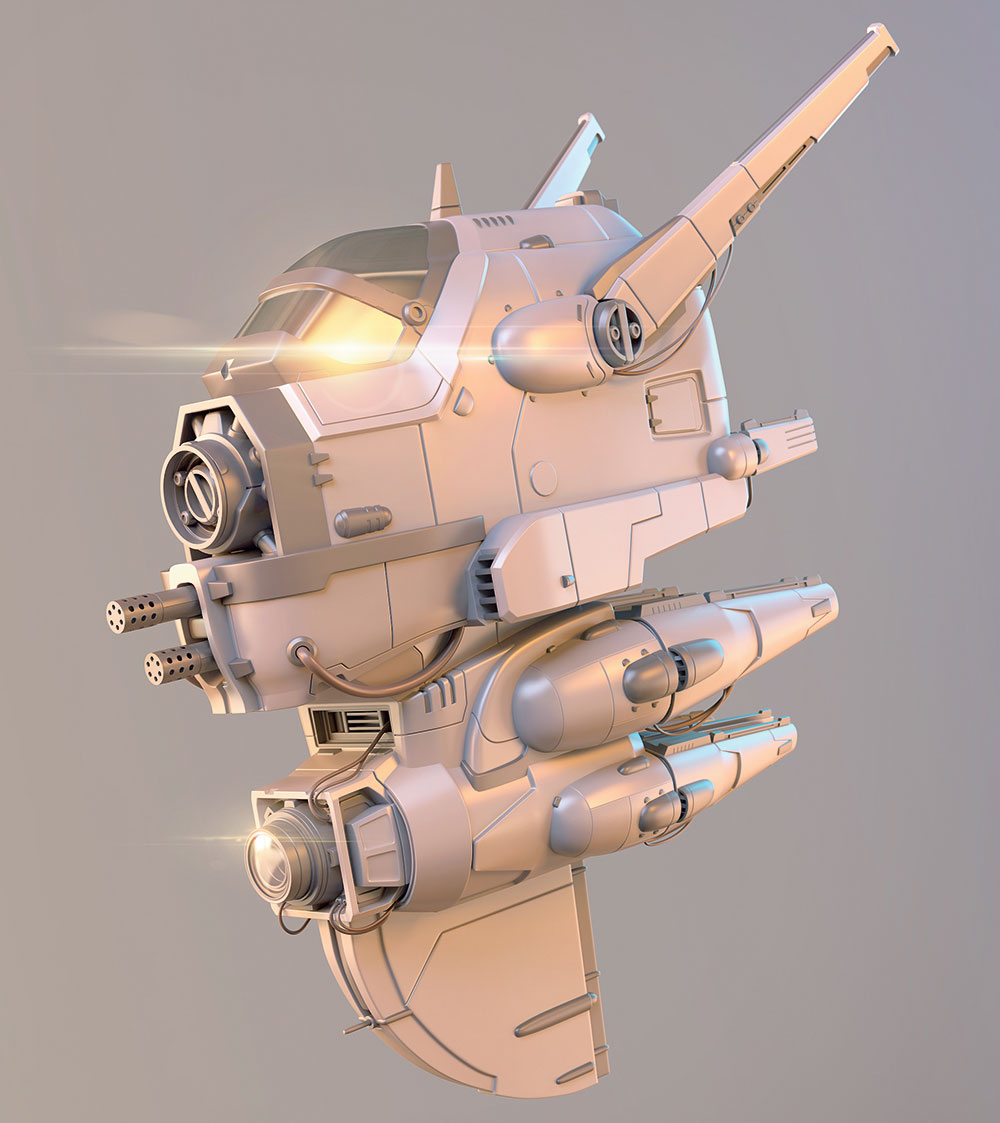
In this tutorial, I'm going to share the techniques and methods I use to create hard-surface models in 3ds Max. I'm going to create a 3D version of US Space Patrol, a sci-fi drop ship concept, made by designer and illustrator Virnard Magpantay.
The main goal of this tutorial is to show you how you can create any hard-surface piece using simple tools in 3ds Max (although some of the techniques can be applied to other modelling software). We'll also look at how to create a clean and organised model to fit into a production pipeline.
I hope you find my tricks and tips useful for making your own models. You can download a video walkthrough of the entire process here, and the files you'll need are here. Also see our 3ds Max 2017 review.
01. Evaluate and interpret the concept
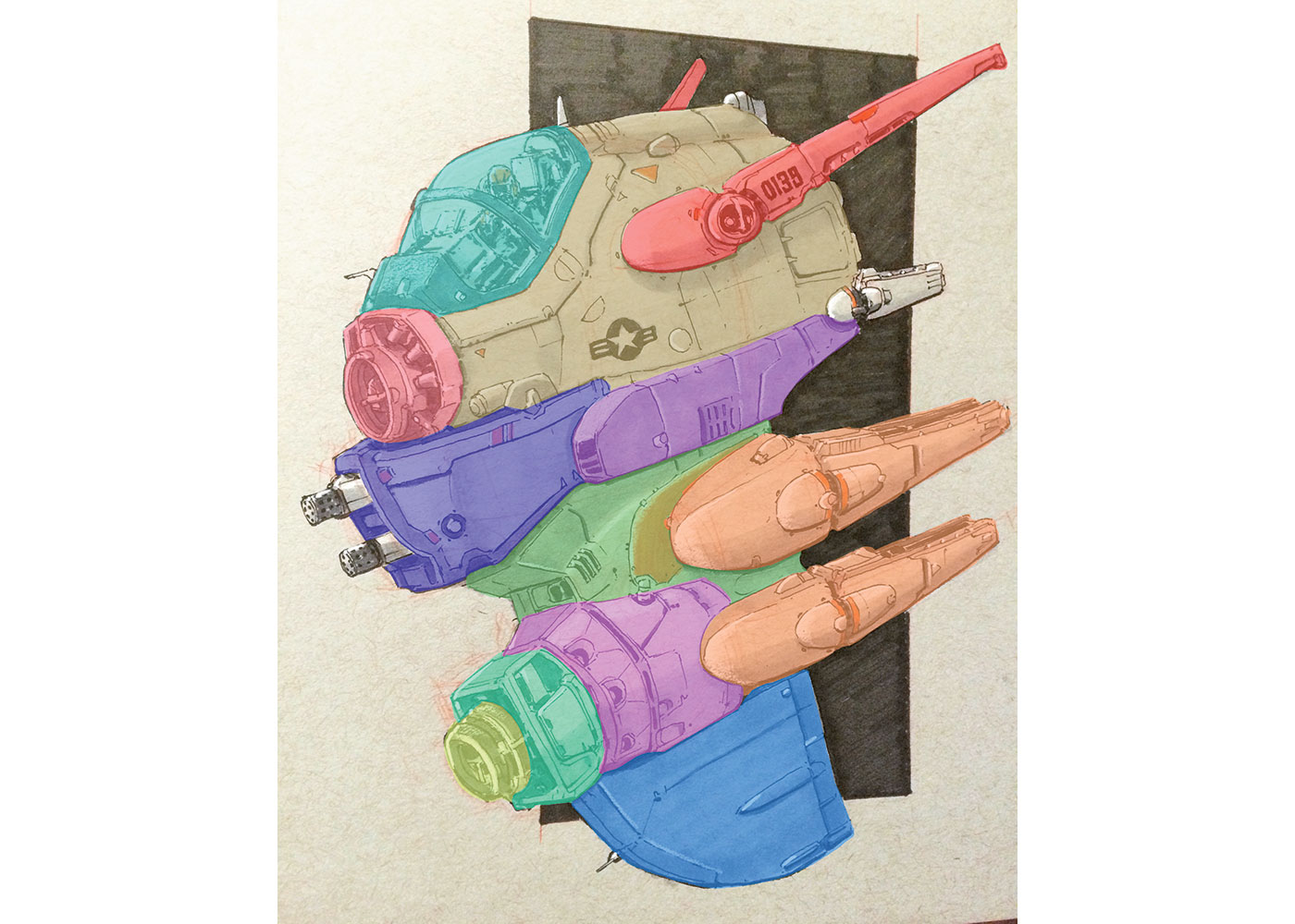
Before starting to do any modelling, I always make sure to evaluate the concept, so let's first decide how we are going to break down the model into the different meshes. It is extremely helpful to start the modelling with a good plan of what you are going to do, it will save a lot of time and effort. It is also a good idea to do some research and gather reference images to help in the development of the shapes.
02. Create the base mesh
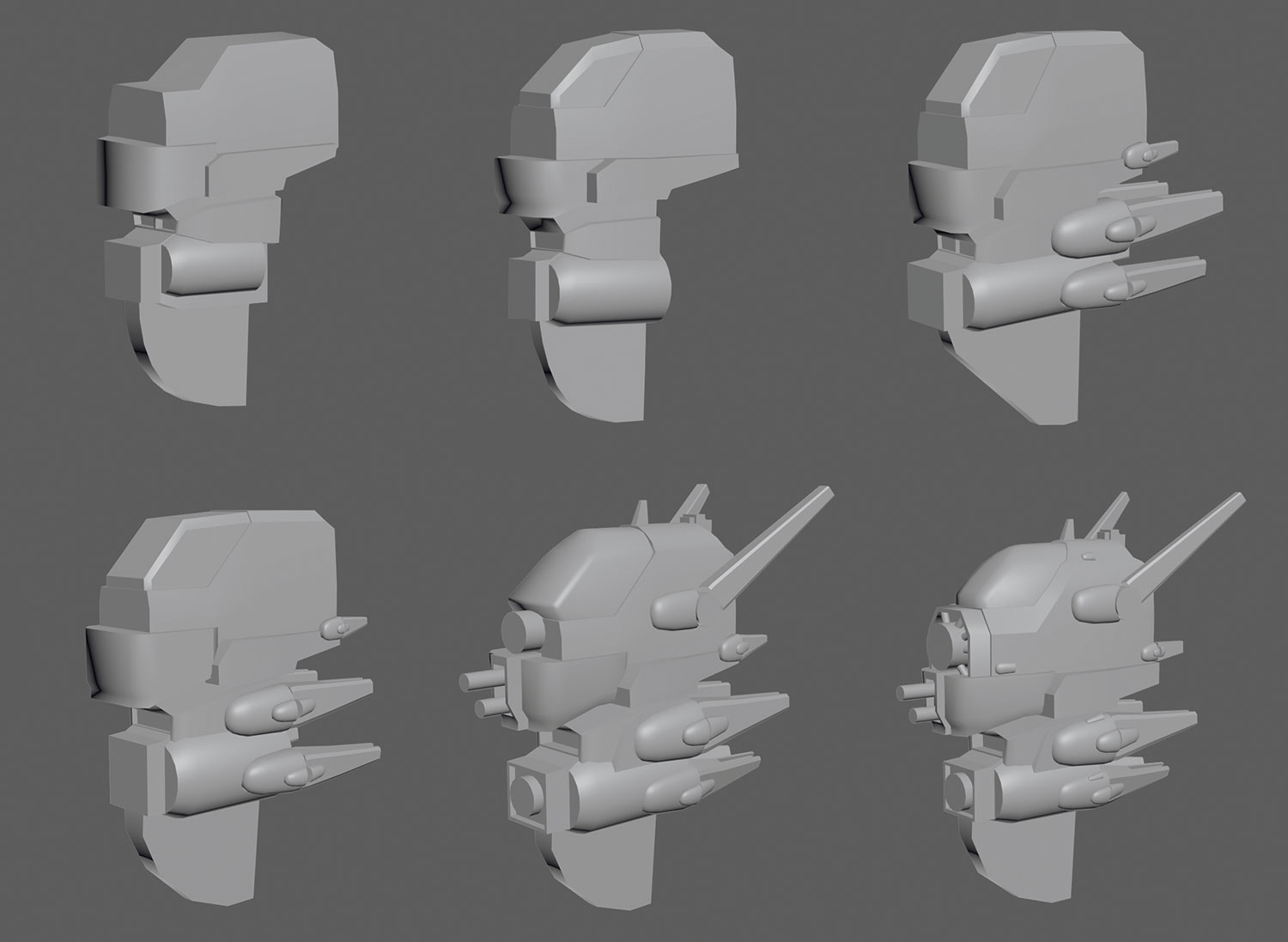
The first thing to do is to create the base mesh of every piece on the model. At this point we are not going to add any detail. Instead, we're paying attention to the silhouette. Establishing initial proportions and gesture is crucial.
It is true that the model's proportions are going to change a lot from the start to finish, but having a solid initial base mesh is a good idea. At this point, we don't have any details on the model so it is easier to play around with proportions.
03. Avoid triangles
When creating a high-resolution model, avoid using triangles as they are likely to give you a terrible result in some areas when a smoothing is applied. If you really must use them, then hide them in areas that can't be seen. As a general rule, using four-sided polys (quads) – even Ngons are better than tris.
Get the Creative Bloq Newsletter
Daily design news, reviews, how-tos and more, as picked by the editors.
04. Create the cockpit
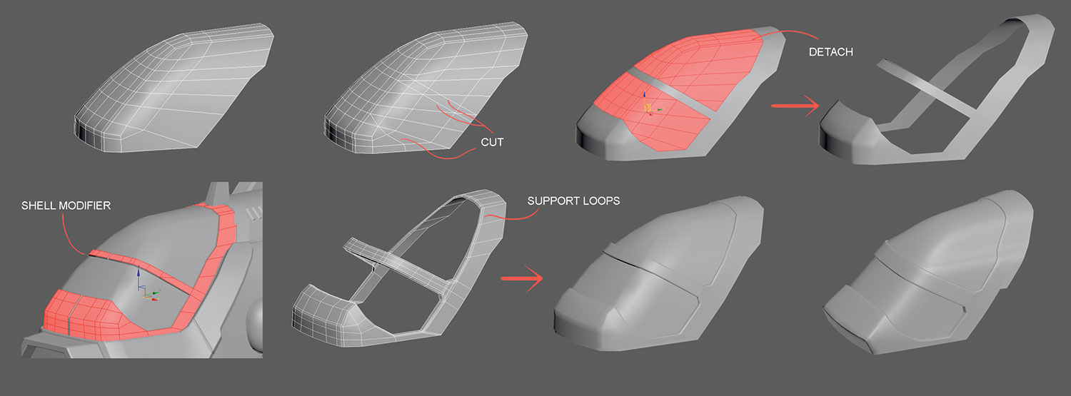
We need to separate the glass from the metal frame area, so let's take the base mesh and make some cuts that suggest the shape of the glass. Once we have the desired shape we can detach the glass object. Now we just need to apply a Shell modifier to the metal frame, and finally we can make some adjustments to the shapes and add supporting loops for the final smoothing.
05. Use connections and bevels
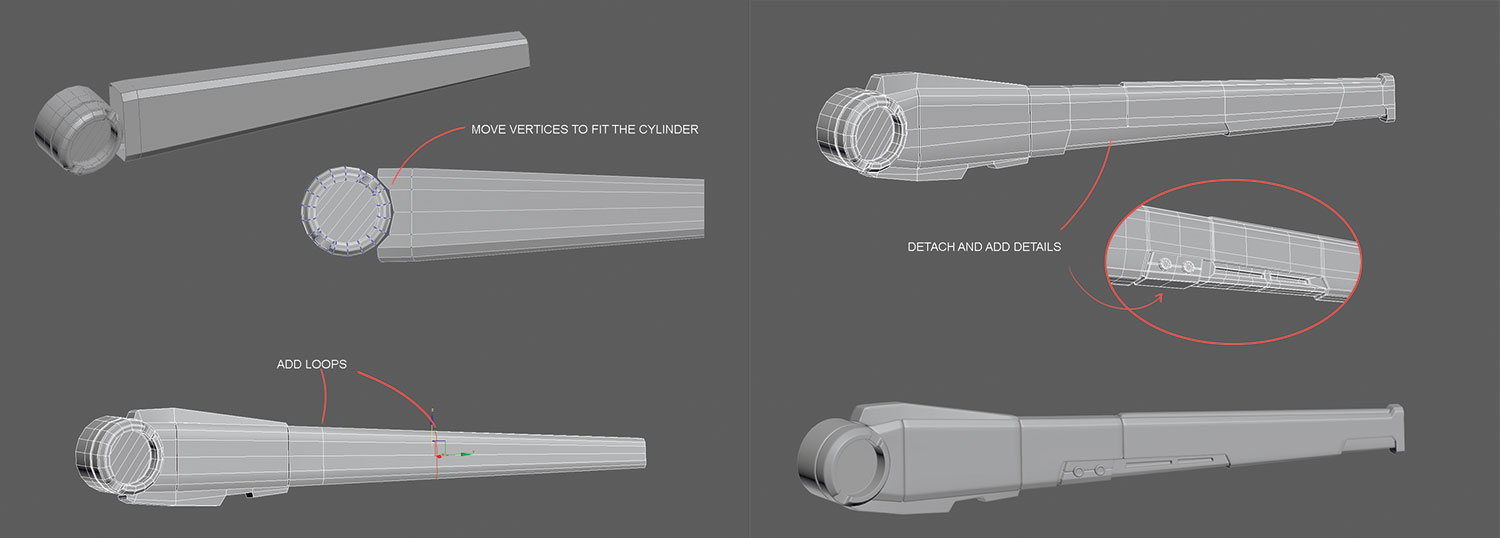
Now take the base mesh and start by making some connections, and move the vertices from one side to fit the shape of the cylinder. Make some edge connections along all the long geometry; this will help make it easier to select different polygons, add bevels, select one loop of edges over another and make extrusions to suggest some paneling. Take the polygons at the bottom, make a bevel and detach them, and add more details to that area.
06. Make vents
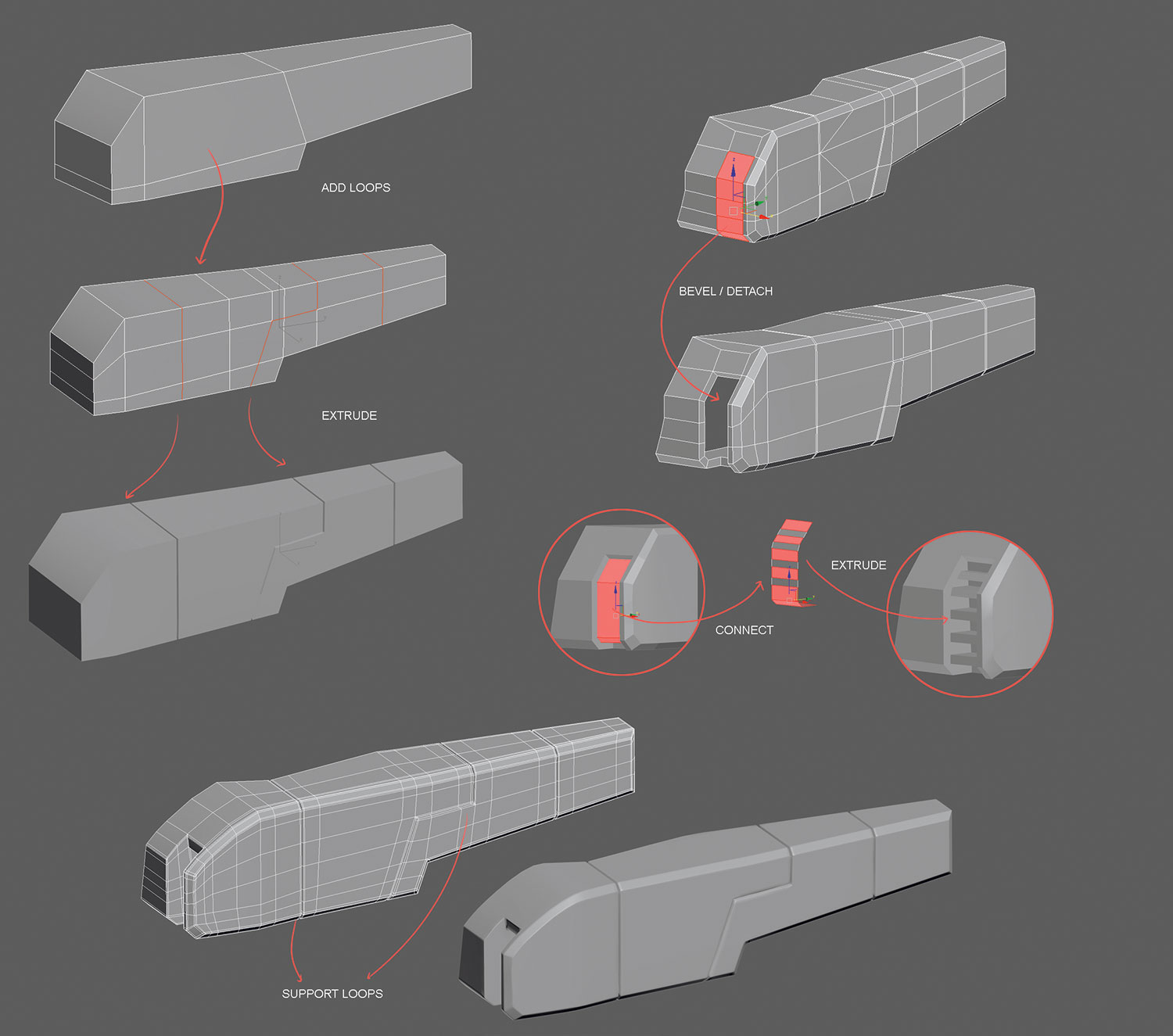
Take the base mesh, add some loops and select some edges to apply an extrusion. To give a more bevelled finish to this piece, select all the edges of the borders and make a big chamfer. Using the same Bevel/Detach technique as before, we can build the front area of the vents. Now take the detached polygons and make some connections, then select the polygons and extrude them to create the vents. Finally, add the corresponding supporting loops.
07. Add edge loops to support the smoothing
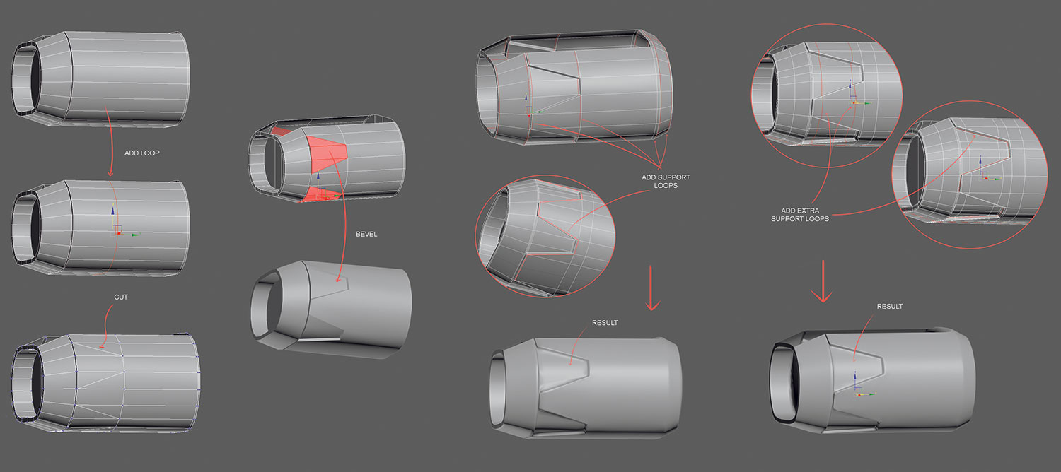
Use the same method of edge connect, cuts and bevels to add more details. Once this is done, it's time to add some extra loops to support the final smoothing. We need to add loops very close to the edges we want to be sharp. After this first group of loops is done, add another set of loops, this time not as close as the first ones; these will be an extra support to avoid the feeling that the geometry is stretched.
08. Cleaning up unnecessary vertices
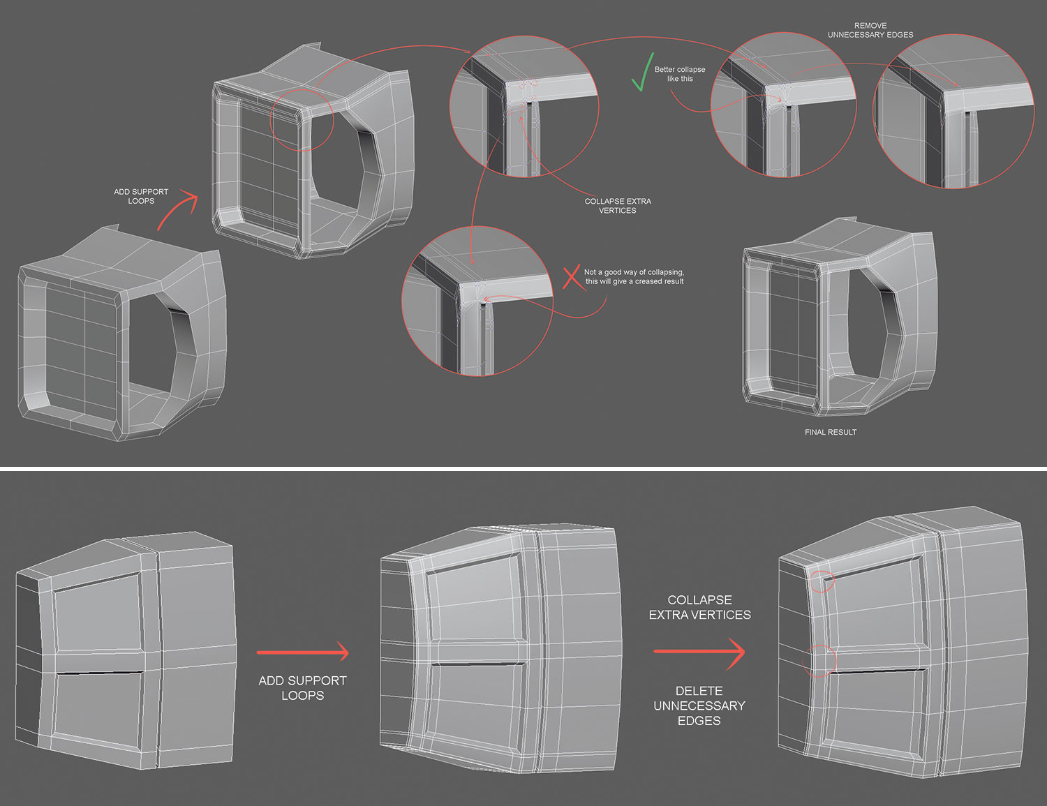
After adding all the supporting loops, we may end up with a lot of edges around the model that we don't actually need. It is a good idea to make a cleaning pass and remove these so we will have a better smoothing result of the geometry at the end. To do this, check the model and start collapsing all the vertices that don't contribute on the support task and in no time at all you'll have cleaner geometry.
09. Model the bottom wing
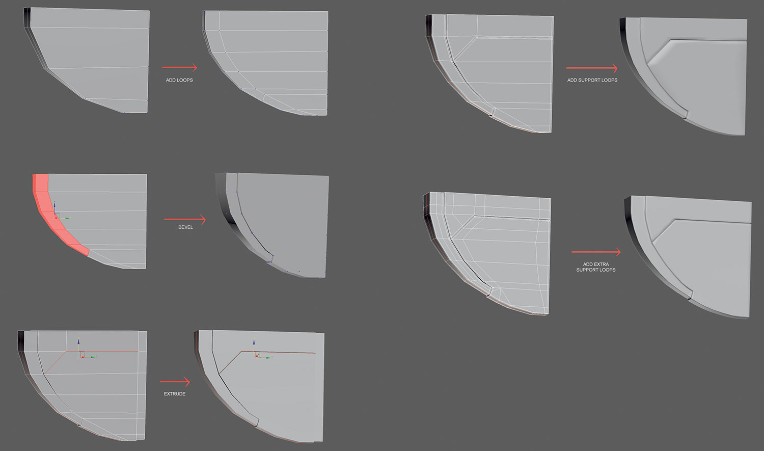
So far, we have suggested a very simple geometry for the bottom wing, now go on and add extra loops to give it a more rounded shape. Add one loop, select some of the resulting polygons and apply a bevel.
Now repeat the same process in the rear area of the model. Select some edges and extrude them to suggest some panel shapes. Once this is done, it is time to add the supporting loops and finally execute the vertices cleaning pass.
10. Make holes in a cylinder
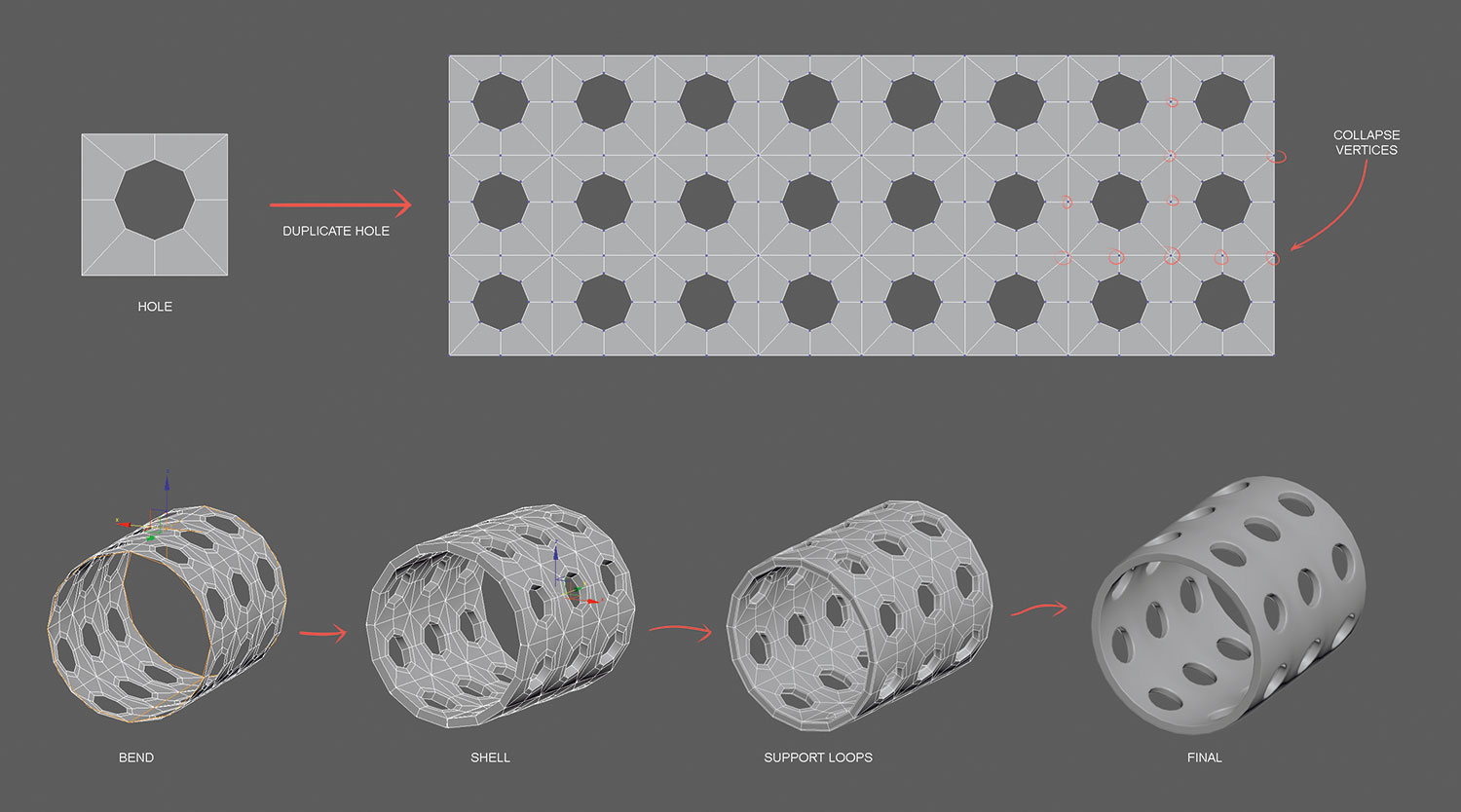
When we want to add holes in a cylinder, people typically think of taking the cylinder and making the holes on it, but this will ultimately result in bad smoothing. Instead, here is a simple technique I like to use: take a cylinder, make a hole, duplicate it (collapse the vertices between holes) and apply a 360-angle Bend modifier. Apply a Shell modifier to add some thickness, and add the support loops. Now if you smooth it, you will have a perfect cylinder with perfect holes.
11. Add geometries on intersections

Details matter when creating an imaginary vehicle that needs to feel authentic and workable. For example, in the areas where two meshes intersect, it is a good idea to add extra geometry to suggest a point of attachment and a more realistic finish: I attached a bevelled inset section to suggest a connecting point.
12. Small pieces
When creating small details like joints or bolts, duplicate them around the model rather than making a new one each time.
This will for help bring consistency to your model, and it will save you precious time. Also, when duplicating elements, make them instances so all of them will take any changes you make.
13. Make cables
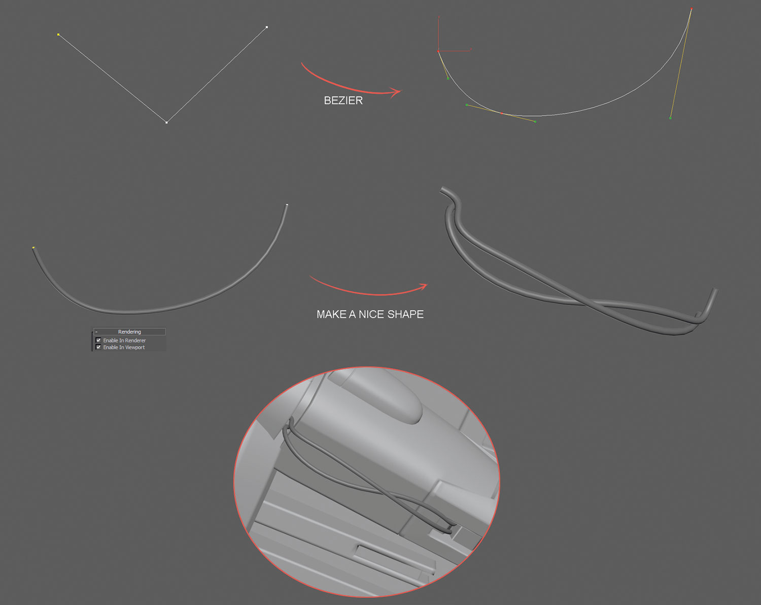
Once the model is done, it is time to add some cables. Make a simple line of three vertices (for small cables) and add a Bezier. Now start moving the vertices and the Beziers until we have the shape we want. An easier way to work with Beziers in this case is to set up the Reference Coordinate System to Screen.
This article originally appeared in 3D World issue 217; buy it here!
Related articles:

Thank you for reading 5 articles this month* Join now for unlimited access
Enjoy your first month for just £1 / $1 / €1
*Read 5 free articles per month without a subscription

Join now for unlimited access
Try first month for just £1 / $1 / €1
