How to model concept art in Cinema 4D
A guide to designing vehicle concept art for a PlayStation 4 game.
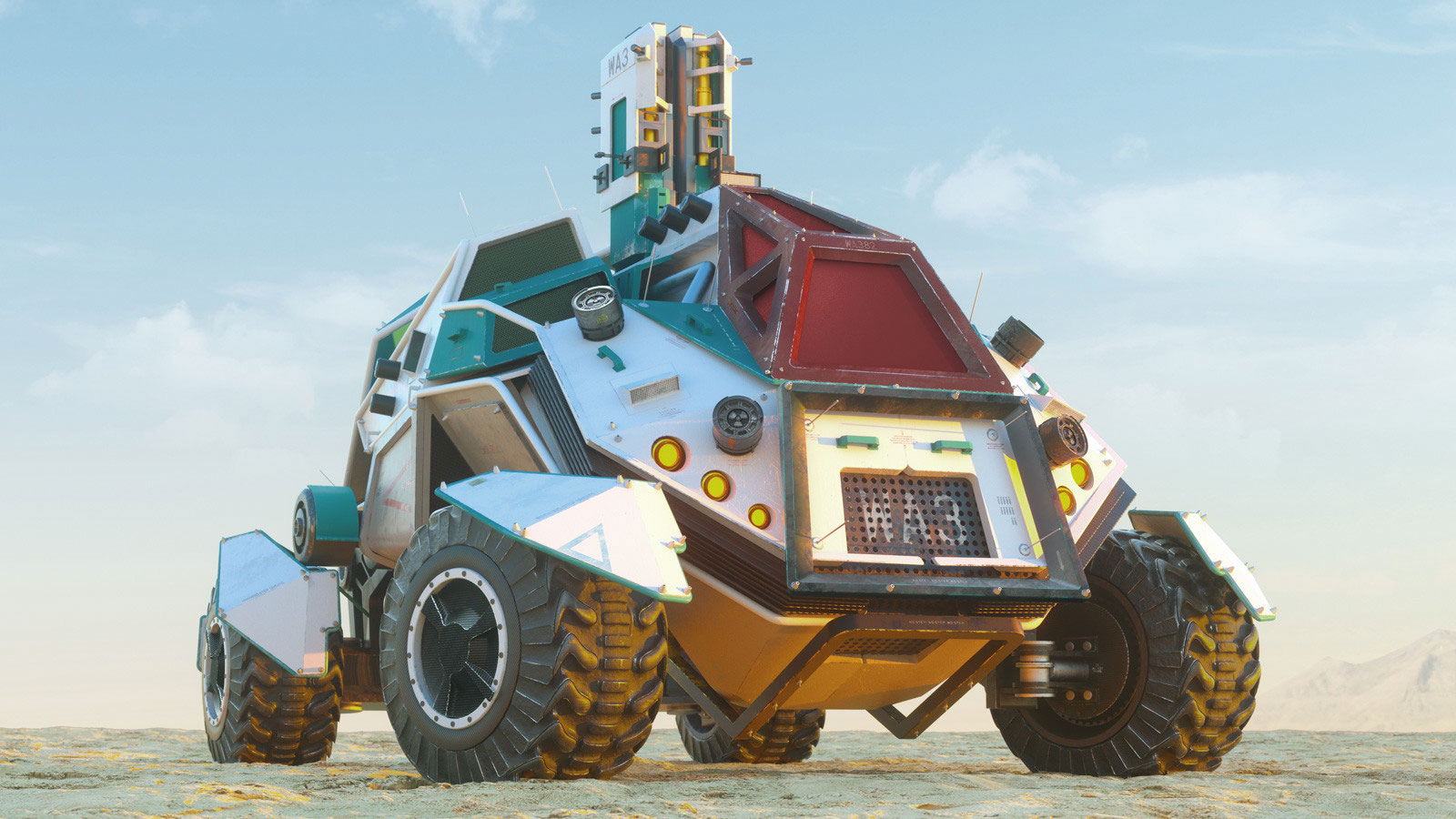
A few years ago, the art director of Lucid Games asked me to help them design 10 independent vehicles for a 4x4 ground-based combat game to be published on PlayStation 4.
After I made a proof of concept for them, they gave me the go-ahead on nine other cars. In this Cinema 4D tutorial, I'll show you my general approach on one of the vehicles.
01. Make a simple sketch
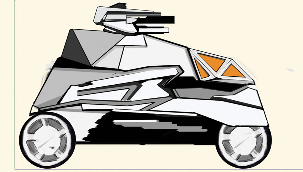
Before starting to work in 3D, I first make a simple sketch of my idea in Photoshop CC. This is a good way to begin, as it's nice to have the size and some proportions ready before we start modelling. I suggest that you try to put a good amount of time into this initial step, rather than just starting completely from scratch in 3D.
02. Set up your scene
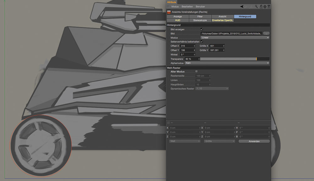
Once I set up the background with my sketch I can go ahead and scale everything to the correct sizes. It's best to work with real-world sizes as this comes in handy when rendering later.
An easy way to do this is to think of, as an example, how large the wheels should be in real life. Just take a circle spline object and type in the required size (that you considered before). In the viewport preferences, you can manually scale up the background image to the preferred size – referring to the circle spline as a reference.
03. Block out geometry
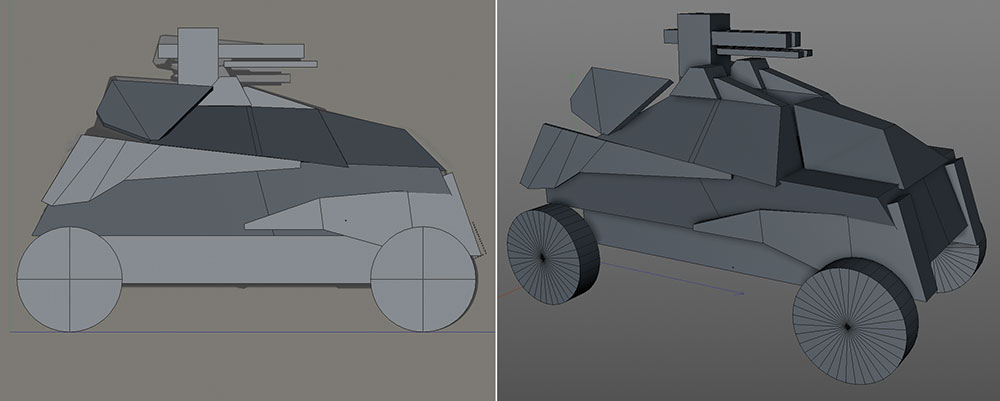
As we now have our scene set up nicely, we can go ahead and block everything out. It's basically like laying everything out for the first time in 3D. There's no need for any special techniques here; just do it the way you are most comfortable with. You can even use primitives and stack everything together as you like.
04. Activate shadows
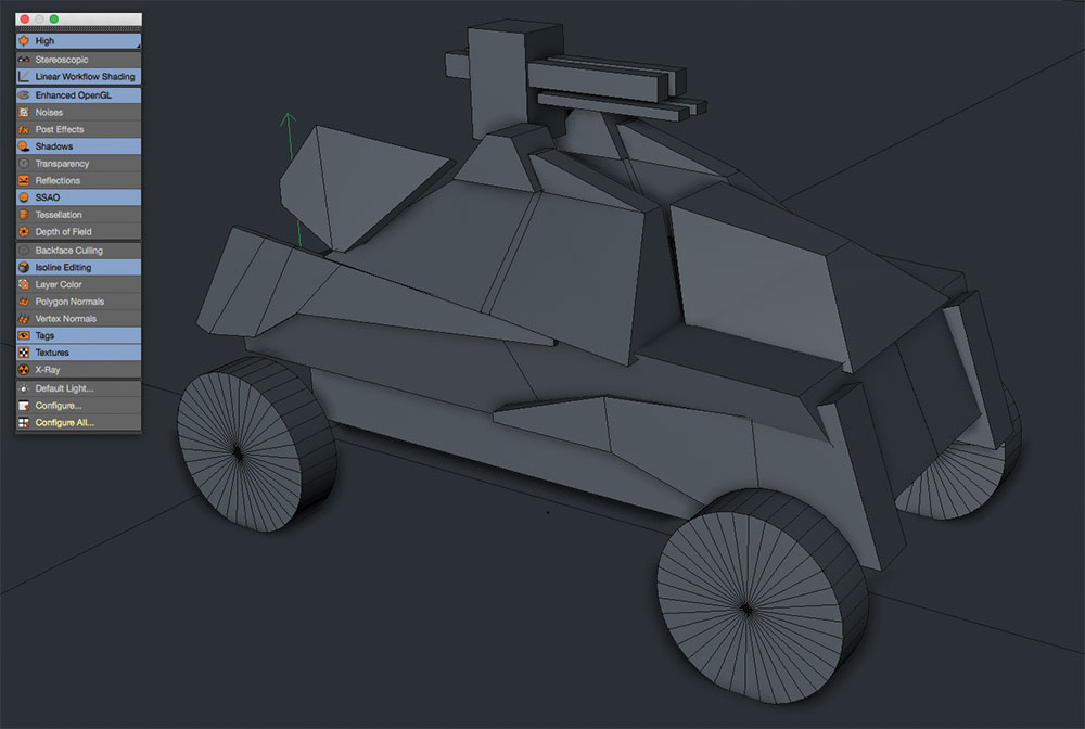
A nice little helper when fiddling out a design is activating visible shadow in your OpenGL viewport. Just use a simple light and activate Shadows in the light source as well as in your viewport. Position it so that the light source casts a nice shadow. It's fast, effective, and without rendering, you can get some good results in the very first stage of modelling and design.
Get the Creative Bloq Newsletter
Daily design news, reviews, how-tos and more, as picked by the editors.
05. Placeholder objects
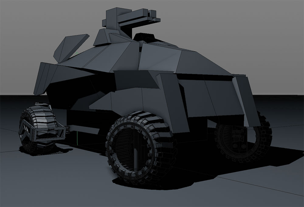
If you are set with your blocked-out design and everything is approved by you or by your client you can go ahead with detailing. I leave out the wheels at this stage because I normally do them towards the end. At this stage, you can use placeholder wheels from other projects if you like, or just use dummy objects or primitives for this.
06. Model the cockpit
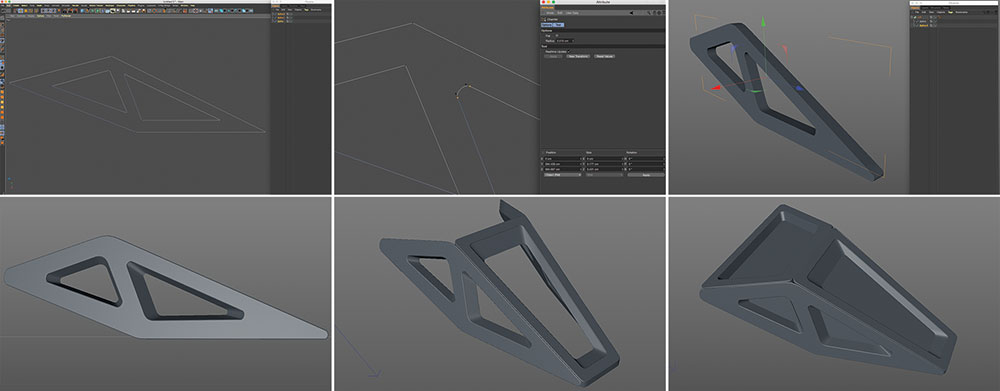
Using the reference drawing, I start to create the cockpit. The method described below works best for me, but there may be other alternatives that may be better suited for your way of working, or that may result in cleaner meshes – but as this is just for a design, I am satisfied with the result.
The first step is drawing a spline with the shape of the side cockpit. Then draw in the window shapes and merge everything down to one spline object. Next, select the edge points and chamfer them on at a point. When you have done this, duplicate the spline object and put the two splines into a Loft NURBS object. Move one of the splines away from the first spline object to gain thickness. Now you can use Fillet Cap in the attributes of the Loft object.
To make your model look more interesting, you can scale down the window shapes of the second spline object. Simply select the spline points (you must be in point mode) and scale them down a bit.
Next put this side of the cockpit into a symmetry object and you're ready to go for the top section. Repeat these same steps with the top and position it correctly over the sides.
As for the windows, just use simple planes that you place inside the windows. They don't need to be cubic objects as we don't want to make them translucent in the end. When you're done with this, group everything that belongs to the cockpit together into one Null Object and name it correctly.
07. Main body parts
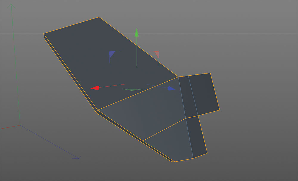
Now we are heading over to the main body, focusing first on the front fender objects, where the lights will be positioned too. Always keep the blockout and the sketch as a reference.
Drop in a primitive object (cube) and make it relatively flat so that it corresponds with the blockout object. Use the cut tool to make cuts at the position where you want to 'bend' the cube. Select the points and 'bend' down the cubic shape following your blockout template. Make sure to angle the points at the front and where you cut it down a little bit.
Use some polyextrudes to make the fender look more appealing. Bevel the corners of the cube and than afterwards bevel the surrounding edge from the top and bottom surface.
08. Detailing
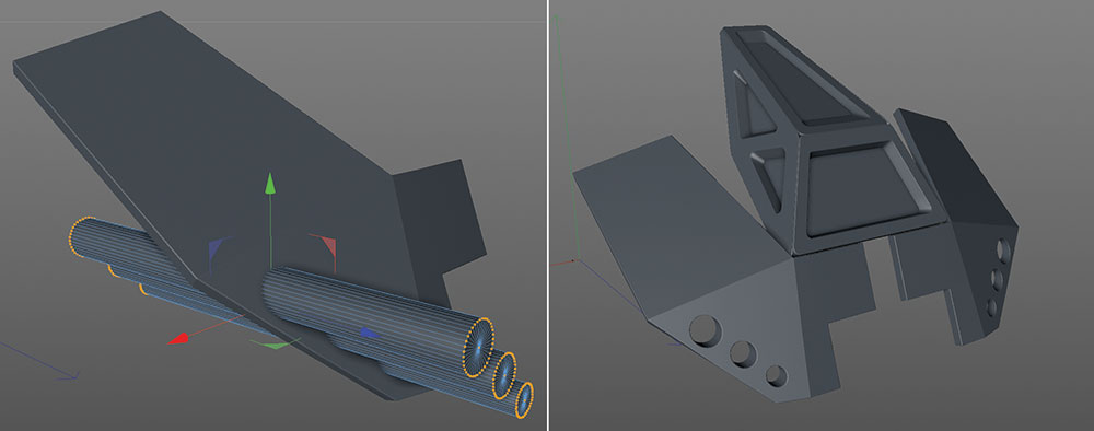
For the holes where the front lights will sit in, I simply used booleans. Just position the negative objects and subtract them with the object. Check 'Create single object' and 'Select intersections'. After converting the boolean with the C hotkey you can double-click the new edge selection icon which appears in the object manager. You can now use this selection to bevel the edge.
Again, group everything together within a null and use a symmetry. Then, simply follow the same technique as described above for the other parts.
09. Model small props
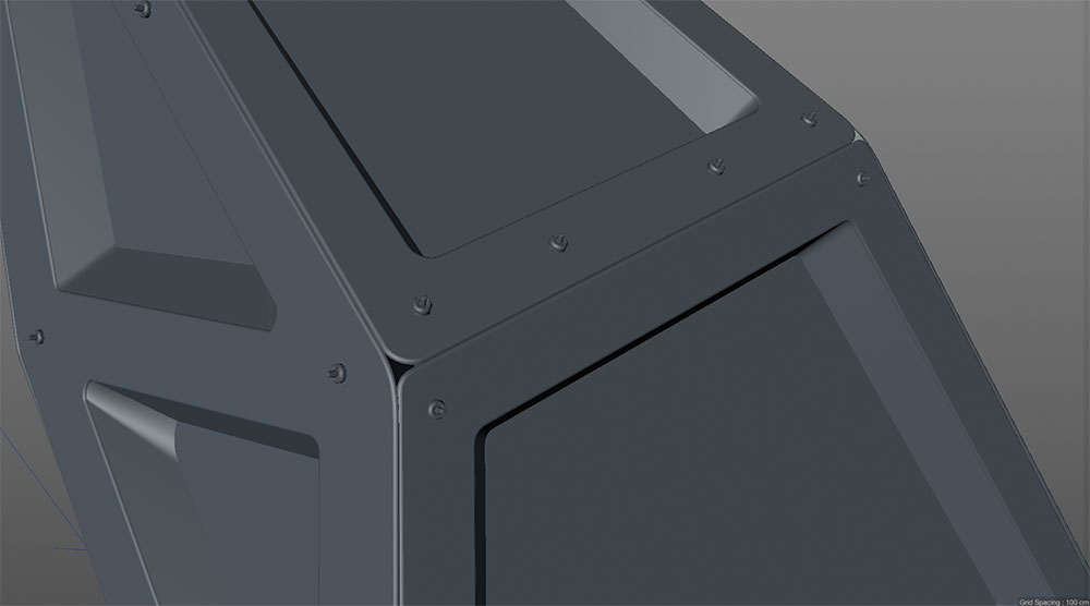
To make the surface a bit more striking, I made a small amount of props, which I placed at some significant and interesting points. These are mostly cylindrical objects, on which I used some polyextrudes and bevels.
10. Suspension system
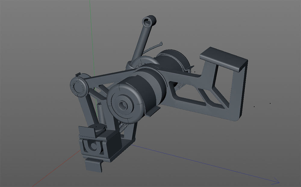
Keeping in mind that the vehicle will be fully movable, I had to figure out a basic suspension system for the wheels. Therefore, I first made some basic beams out of a cube object. To give it more visual interest I modelled in some holes, in order to make it appear more technical and also lightweight. I used Inner Extrude and the Bridge tool, which works really well in Cinema 4D.
Afterwards I added some more extra details like springs and cables, which can be easily done with Sweep NURBS.
11. Attempt wheel design
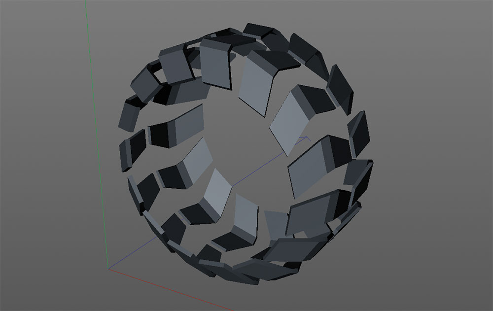
For the wheels I was aiming for a high-tech pattern. I was also keeping in mind that the wheels will spin when driving, so I had to make a pattern that looks appealing while the wheels are spinning.
As I had to do one wheel design for each vehicle (ten in total) I knew this would be a bit challenging. As I had done some wheels before for other designs, there were two different approaches for modelling the wheels.
The first approach is simply building up one piece of the overall pattern and cloning it with a cloner object or an array – this is a very sleek and fast method.
12. Attempt wheels (part 2)
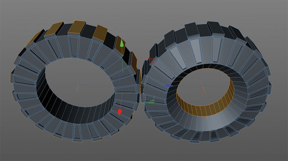
The other technique is utilising a cylindrical object and using the sections with the help of Inner Extrude and Extrude to make something like a pattern. You can split up poly selections and use them as new additional pattern objects, for example.
Alternatively you can use HyperNURBS to smooth everything down. If you do so, you need to set some additional cuts with the knife (Loop Cut), otherwise it will be too rounded.
13. Add interest by filling up the body
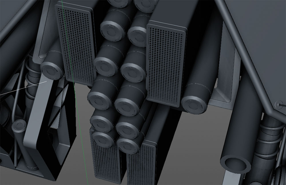
As the viewer will see the vehicle from the rear during most of the game, I had to fill in some extra details in order to make it look interesting. As I had done some stuff before, I made use of some of the geometry and just filled in the additional elements.
14. Save time and re-use parts
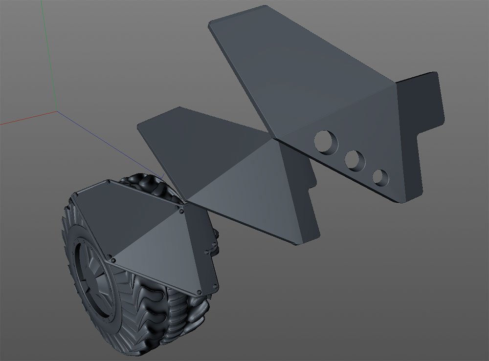
Be aware that, even within the existing model you are creating, you can make use of some of the parts again. For example, I used some of the front fenders as mudguards for the wheels.
15. Simple studio setup
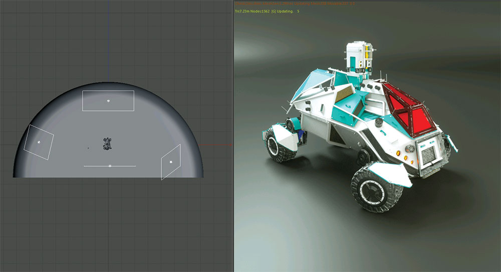
I decided to use two light setups and settings for the final look. For the studio setup I created a standard studio background.
There are many ways to create this. For example, you can draw a spline and rotate it 180 degrees within a Lathe NURBS object. I placed some area lights around the object and used an HDRI to lighten everything a bit. This also gives you some extra nice reflections, instead of merely having the reflections of the area lights.
16. Outdoor scene setup
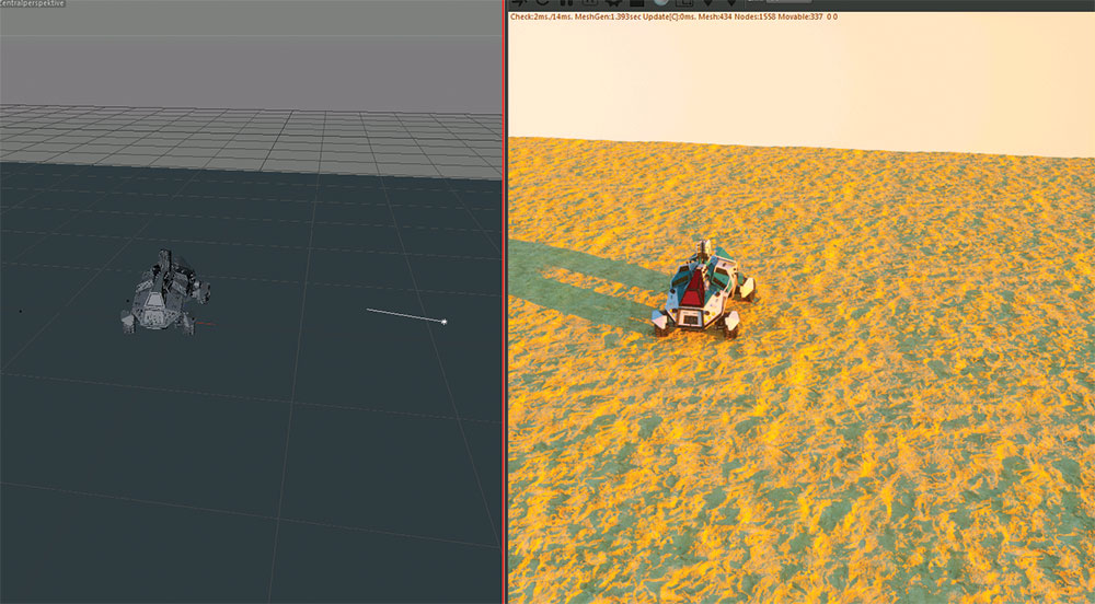
For the other light setup, I thought of creating an outside scenery in the desert. Nothing complicated as I had to be fast in this job. I used a simple Octane Daylight object. I added a ground plane and used some real displacement shaders. This gives you really nice results that look fantastic even in close-ups.
17. Add emotional images
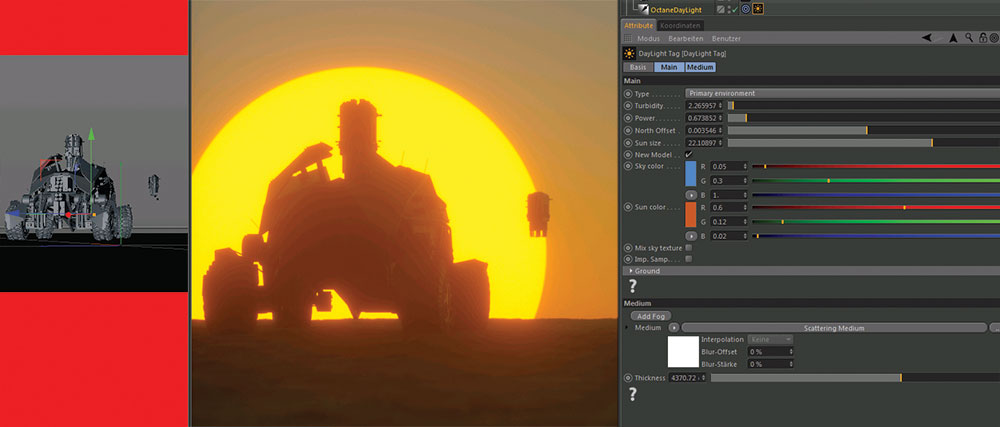
To add some emotion to the scene, I played a bit with the sun size and added some volume fog. In combination with long focal length (100-500mm, like a real-world tele) you can get a very pleasant effect.
Be sure to play around with the f-stop as well, but don't exaggerate it. It can look like a miniature if you use the wrong f-stop values!
18. Octane Dirt node
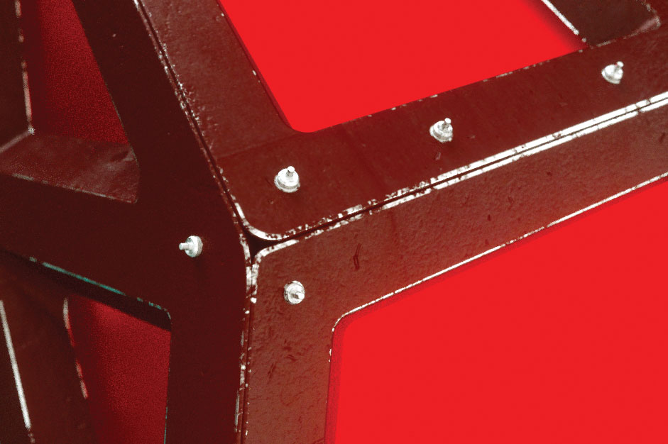
Since I did not do any UV Maps, I used inverse ambient occlusion to create a weathering effect on the edges of some parts. This is fully procedural and works great in Octane with the Dirt node.
You can also combine some noises or a grunge texture to break the used edge up a bit more.
19. V-ray Dirt
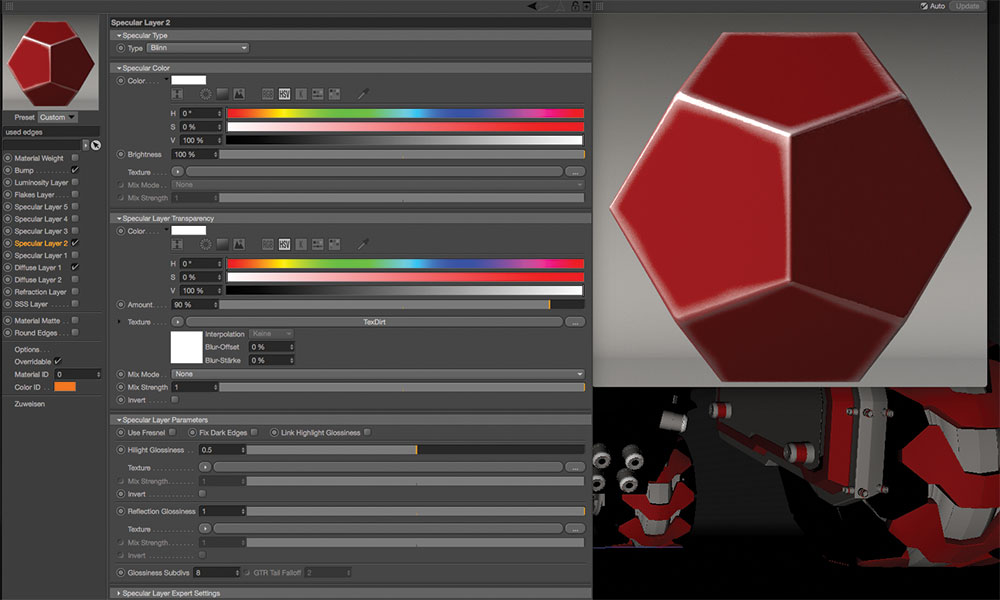
This also works the same way within V-Ray (or any other renderer), although sadly there is no node tree (yet) for setting up shaders like in Octane, but you can get almost the same results. Just use the V-Ray PowerShader and VRayDirt, be sure to check inverse ambient occlusion and you are ready to go.
Like in Octane you can add shaders or textures to bring it a bit more to life.
20. Render settings
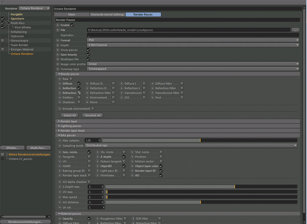
For rendering in Octane I used the default path tracing settings – this works for me most of the time. For post-production I made use of the Octane render layer settings. Be sure to double-check everything you would like to have for your post work, and you're ready to render.
21. Post-production decals
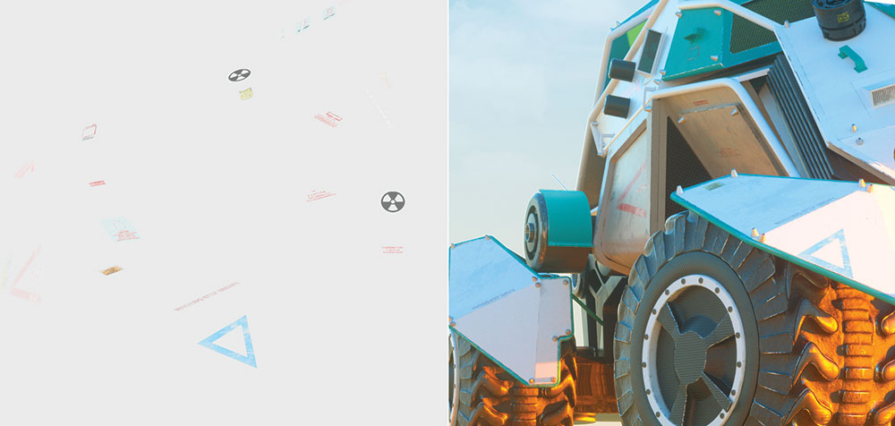
A fast way to apply decals to your render, as long as you have one perspective, is by applying them in Photoshop. It's much faster than dropping them on your model in your 3D app, as you don't have to create a material, alpha, spec map and so on.
So if you have one single shot, this is a real time saver. Just find some decals you like on Google and drag them on your model.
Try out some fill methods and choose the one which looks best. Use the Transform tool in Photoshop to adjust the decals to the correct perspective of the model. You can use some geometry parts as guides for the transform.
Once you have placed it, you can used a grunge brush to make some imperfections. You can also use the layer transparency.
22. Post-production general
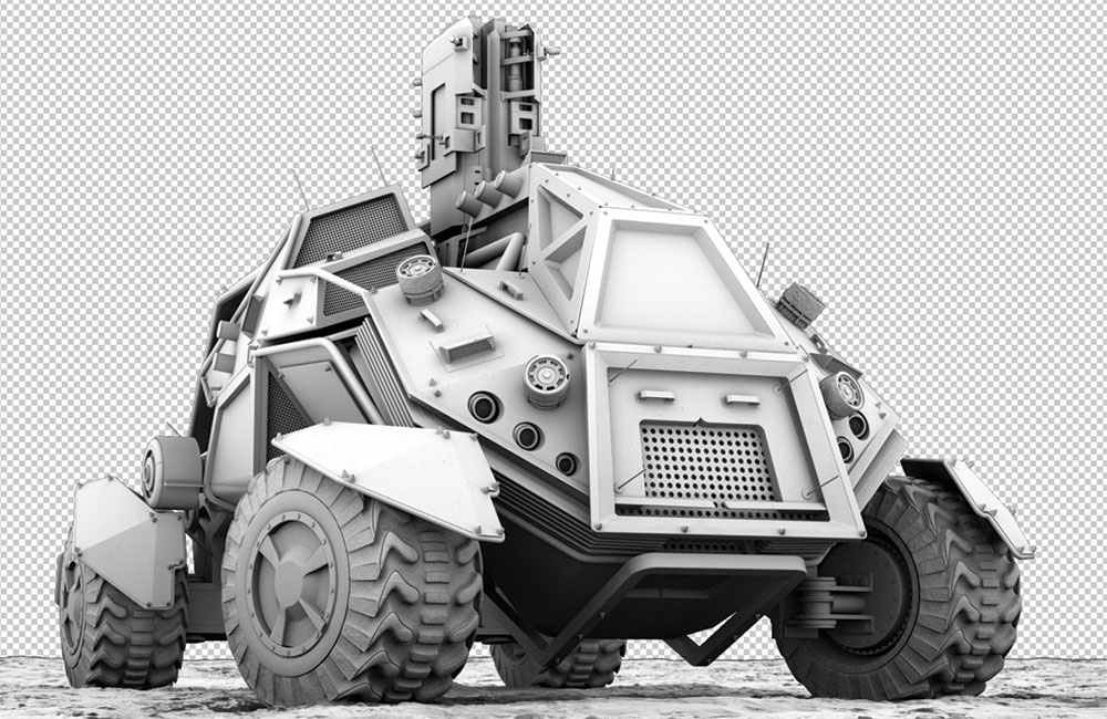
If you are set with your decals, you can do some adjustments with the help of the material id pass. Normally I just do some levels adjustments on a few parts.
Sometimes an ambient occlusion map can come in handy. But don't exaggerate this either – just use a small amount of transparency on this layer and multiply it.
This article was originally published in 3D World, the world's best-selling magazine for CG artists. Subscribe to 3D World here.
Related articles:

Thank you for reading 5 articles this month* Join now for unlimited access
Enjoy your first month for just £1 / $1 / €1
*Read 5 free articles per month without a subscription

Join now for unlimited access
Try first month for just £1 / $1 / €1
