How to make massive explosions with V-Ray
Create a bang with this step-by-step guide to making realistic explosions.
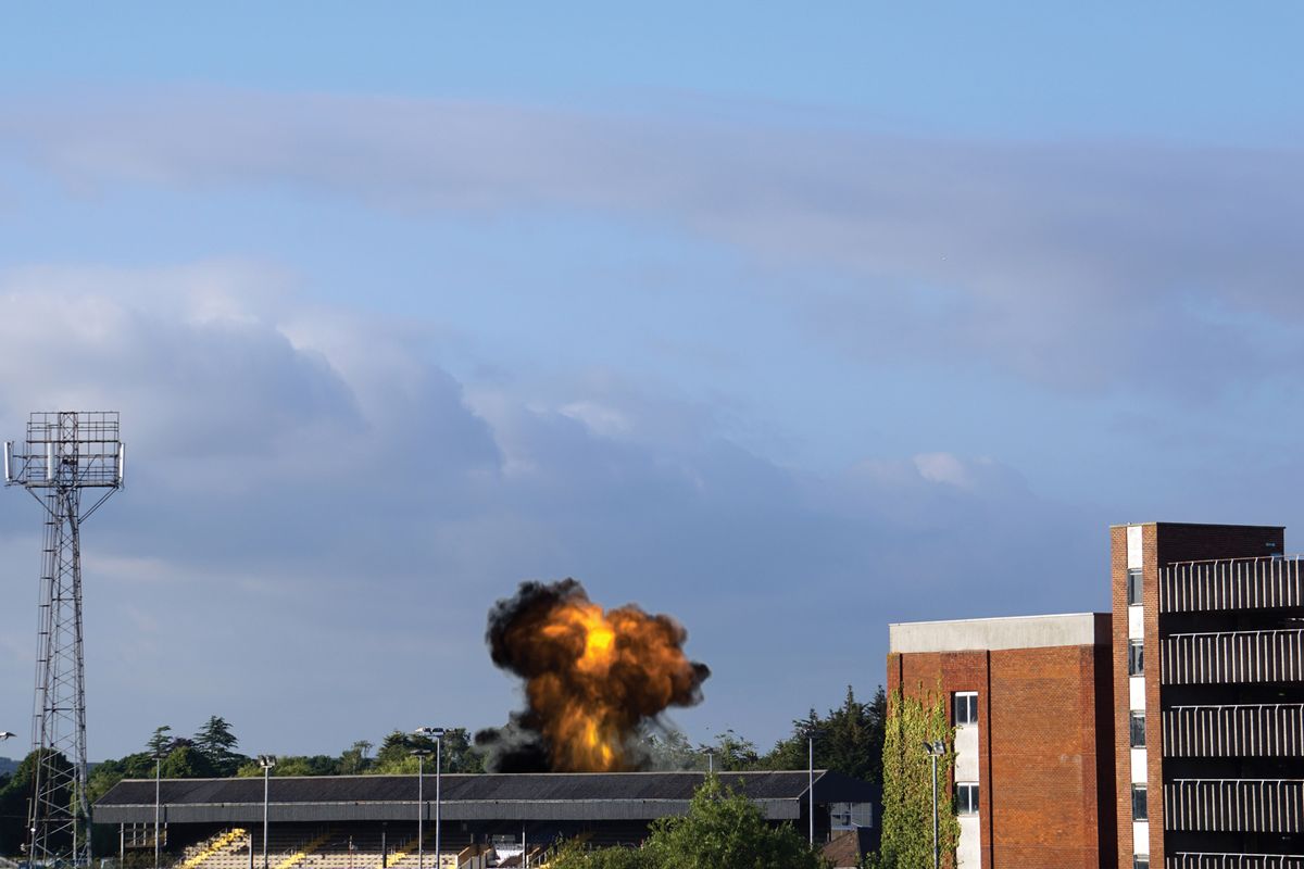
Creating and compositing 3D explosions is usually a task for two different artists or studio departments, but here we'll blur that line by using the V-Ray for Nuke plugin. Instead of working with rendered explosions from a VFX application, we’ll instead show you how to use .vbd files exported from Houdini.
The advantage of this workflow is it allows compositors to work with the explosion’s volumetric data with tools to change the look and orientation of the asset, without having to send back to the VFX artist or department for changes.
Before you start, you'll need to download the relevant files from the 3D World Vault.
- Download the files you need from the 3D World Vault
In the Vault, you'll find that Steven Knipping of Applied Houdini has provided 72 .vdbs. Each .vdb contains (density) containing smoke, (velocity), (heat) where the fire is, and (temperature) how hot it is.
The grids are 300 voxels max in the Y direction to bring down the voxel count and file size, while still providing decent resolution. The provided .hipnc file shows a preview of the .vdb colouring in Houdini and the .mov file is a quick and dirty Quicktime movie preview of a playblast of the .hipnc.
Knipping’s ‘Volume V - Combustion Simulation’ video tutorial on his website covers how to make this.
Now, follow these 12 steps to create realistic explosions in V-Ray for Nuke.
Get the Creative Bloq Newsletter
Daily design news, reviews, how-tos and more, as picked by the editors.
01. Import the explosion
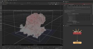
Add a VRayVolumeGrid Node in the Node Graph. In Properties, Input, click the folder icon next to Input Cache File and ensure Sequences is enabled to import all 72 frames.
Go to the Stadium folder and select explosion.appliedhoudini.1.vdb, then click Open. With VRayVolumeGrid1 selected, press [1] to view it. Scrub through the Timeline to see the imported .vdb explosion.
02. Set up V-Ray network
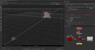
Add a TransformGeo Node to VRayVolumeGrid1’s output. This is useful if you want to rotate or reposition the volume, set rotate y to 180. Add a VrayRenderer Node, pipe its obj/scn input to TransformGeo1.
Add a VrayCamera Node, in its Properties, Axis tab, set translate z to 100 then pipe it to VrayRenderer1 cam input. Add a Constant Node and pipe it to VrayRenderer1 bg input. In Constant1’s Properties, set color to 0.5. Then select VRayRender1 and view it.
03. Set rendering properties
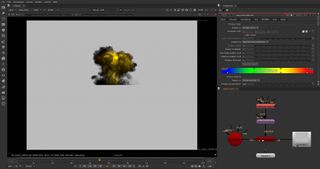
With the cursor over the Viewer Pane, press [Tab] to switch from 3D view to 2D. Scrub through the Timeline to see the explosion smoke plume. In VRayVolumeGrid1’s Properties, switch to the Rendering tab.
The options in this tab control how the VRayVolumeGrid effect is rendered. Set Render preset to Fire/Smoke.vdb from Houdini. This will introduce fire. In Smoke, set Simple smoke factor to 0.6 to adjust the Smoke Opacity.
04. Set up the fire
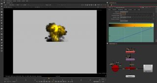
Go to the Fire tab, which controls the emissive colour (fire) of the volumetric shader and the light emitted by VRayVolumeGrid. The Physically based parameter can produce either an artistic look (value 0) or realistic physically based intensity (value 1).
A higher value means strong brightness for the hot parts of the fire. Set Physically based to 0.8. Set fire multiplier to 1.
05. Fine-tune the fire
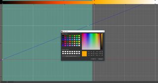
Fire Color and Opacity/Intensity in the Fire tab has a gradient for controlling colour and a curve for setting intensity or opacity. Click Expand (bottom right) to get a larger window.
From the left, leave slider 1 as is. Select slider 2 and put it at 10. Right-click the slider>Change Selection Color and choose an Orange shade. Put slider 3 at 15, with its Hue at 39. Put slider 4 at 25. Hit Play.
06. Render the explosion
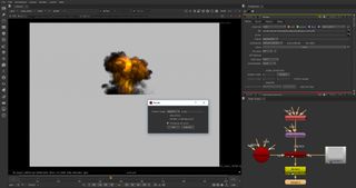
To make the Nuke network lighter, render the explosion as a .tiff sequence. Pipe a Write Node to VRayRenderer1. In its Parameters, set channels to rgba.
Click the folder next to the file and choose a folder to render to. Append the file path with Explosion.###.tiff (filename/frame padding/file format) and click Save. Set compression to none and click render. In the pop-up Render dialog, change the Frame range to 1-72, then click OK.
07. Lighten the network
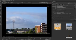
Select File>Clear to clean the Nuke Node Graph. Add a Read Node, go to the Stadium folder and select backplate Stadium.jpg, then Open. With the backplate selected, press 1 to create a Viewer and view it.
Select Edit>Project Settings and change full size format to 6000 x 4000 to match the backplate resolution. Set frame range to 1 and 72. Add another Read Node and use it to bring in the rendered explosion .tiff image sequence.
08. Comp the explosion

Add a Premult Node and pipe to the explosion Read Node to multiply the explosion sequence’s RGB channels by its Alpha. Then Add a Merge Node and pipe its A input to Premult1 and its B input to the backplate Read Node.
Select frame 41, view Merge1 and you’ll see the explosion is composited over the backplate. Add a Transform Node and a Crop Node to the network as shown in image 08. With Crop1 selected, press 1 to view.
09. Position the explosion
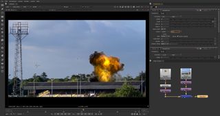
In the Crop1 parameters, set r to 1920 and t to 1080, and enable reformat. Open the Transform1 Node’s Properties and either reposition the backplate manually with the Transform Handle or set translate x to -1110; translate y to -560; scale to 0.6; center x to 1500; center y to 1000.
Add a Transform after Premult1 and view Merge1. Reposition manually with the Transform2 Handle or set translate x to 315; translate y to -568; center x to 1044; center y to 928.
10. Roto the roof
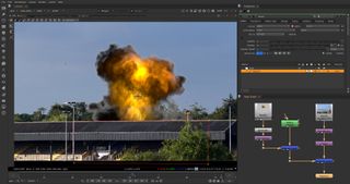
With Transform2 selected, add a Merge Node. This will automatically pipe using the A input. Open Merge2’s parameters and set operation to out. Deselect Merge2, add a Roto Node.
View Crop1 and select the Roto’s Bezier Tool. Click to place points along the ridge of the roof and at the bottom of the backplate to form the shape pictured. Pipe Roto to Merge2’s B input, View Merge1.
11. Match colour
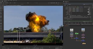
Pipe a Grade Node between the explosion Read Node and the Premult1 Node. We will use this to adjust the explosion to better integrate the blackest and whitest points with the backplate. Click the colour swatch alongside lift, hold [Ctrl] and pick the darkest pixel on the black plate.
Repeat for Gain but pick the brightest pixel. Using the gamma slider in the Viewer helps identify the darkest and lightest pixels. For fine-tuning, experiment with both the multiply and gamma values in the Grade Node.
12. Output the render
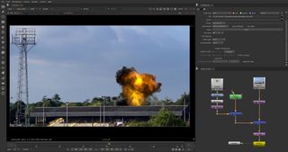
Usually the blackpoint and whitepoint don’t need to be adjusted. You can add a Saturation Node after Merge1 and set saturation to 0, then fine-tune these values before deleting the Saturation Node.
Add a Clamp node after Merge1 to constrain RGBA between 0 and 1. Select the Crop1 and press [Ctrl]+[Shift]+[X] to extract from the network and pipe it after the Clamp. Pipe a Write node to the Crop1 and refer back to Step 06 for the process of rendering out the sequence as a .tiff sequence. Your explosion should now be ready.
This article originally appeared in 3D World issue 224. Buy it here.
Related articles:

Thank you for reading 5 articles this month* Join now for unlimited access
Enjoy your first month for just £1 / $1 / €1
*Read 5 free articles per month without a subscription

Join now for unlimited access
Try first month for just £1 / $1 / €1
