How to kitbash on the go with Shapr3D
Learn how to use Shapr3D to kitbash on an iPad Pro with this handy tutorial.
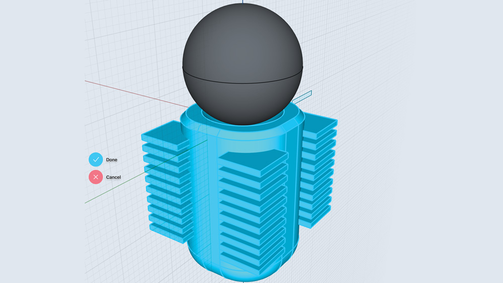
Shapr3D is a great tool for kitbashing. It helps to literally bash out ideas and produce useful pieces of kit. It’s fast, clean and its interface is very intuitive; this is definitely the direction I see the 3D industry moving to – not larger, more powerful machines, but more accessible, more usable software, available in VR and AR, and on mobile and tablet devices.
Kitbashing is nothing new, but making perfectly usable, pipeline-friendly kitbash pieces on an iPad is new. In this tutorial you will learn how to make three kitbash pieces in Shapr3D on the iPad Pro (see our best Black Friday iPad deals ahead of the big day). The first part will cover the creation of kitbash pieces on the iPad, and the second section will show how to use those pieces to create vast skyscrapers and cityscapes in a matter of hours.
For some 3D inspiration, check out our roundup of the best 3D art out there.
Kitbash Piece 1: Girder
01. Get started
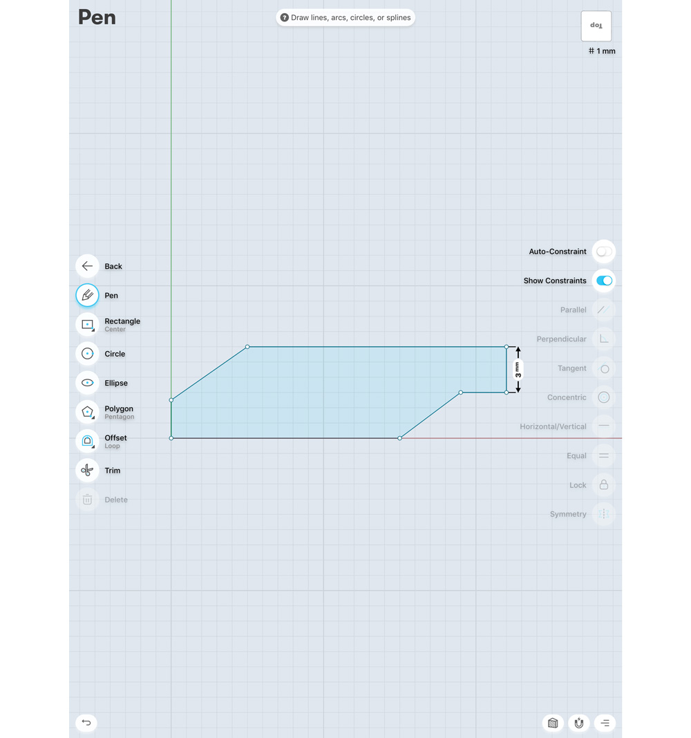
Create a new project by selecting the Start Designing option in the top right. You can navigate with your finger to rotate the 3D view, but let’s start by switching to a top-down view. Select the view cube in the top right-hand corner, then choose Top. From this angle, I want to draw out a plan for the silhouette of our shape. Here I’m going to make a basic girder. At this stage I’m not concerned with scale.
02. Delete offcut edges
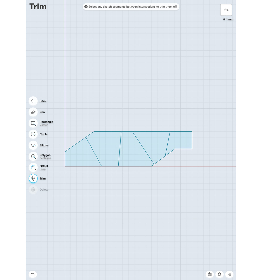
Using the sketch tool, slice lines through the shape, then select Trim from the tools button, and select all the offcut edges to delete them. Then select Offset from the tools section. Now with your pencil drag it away from the edge of each of your divided sections; in this example, I’m going to drag it -0.7mm (I’m making a note of this measurement as I want all my offsets to be the same).
03. Make it 3D
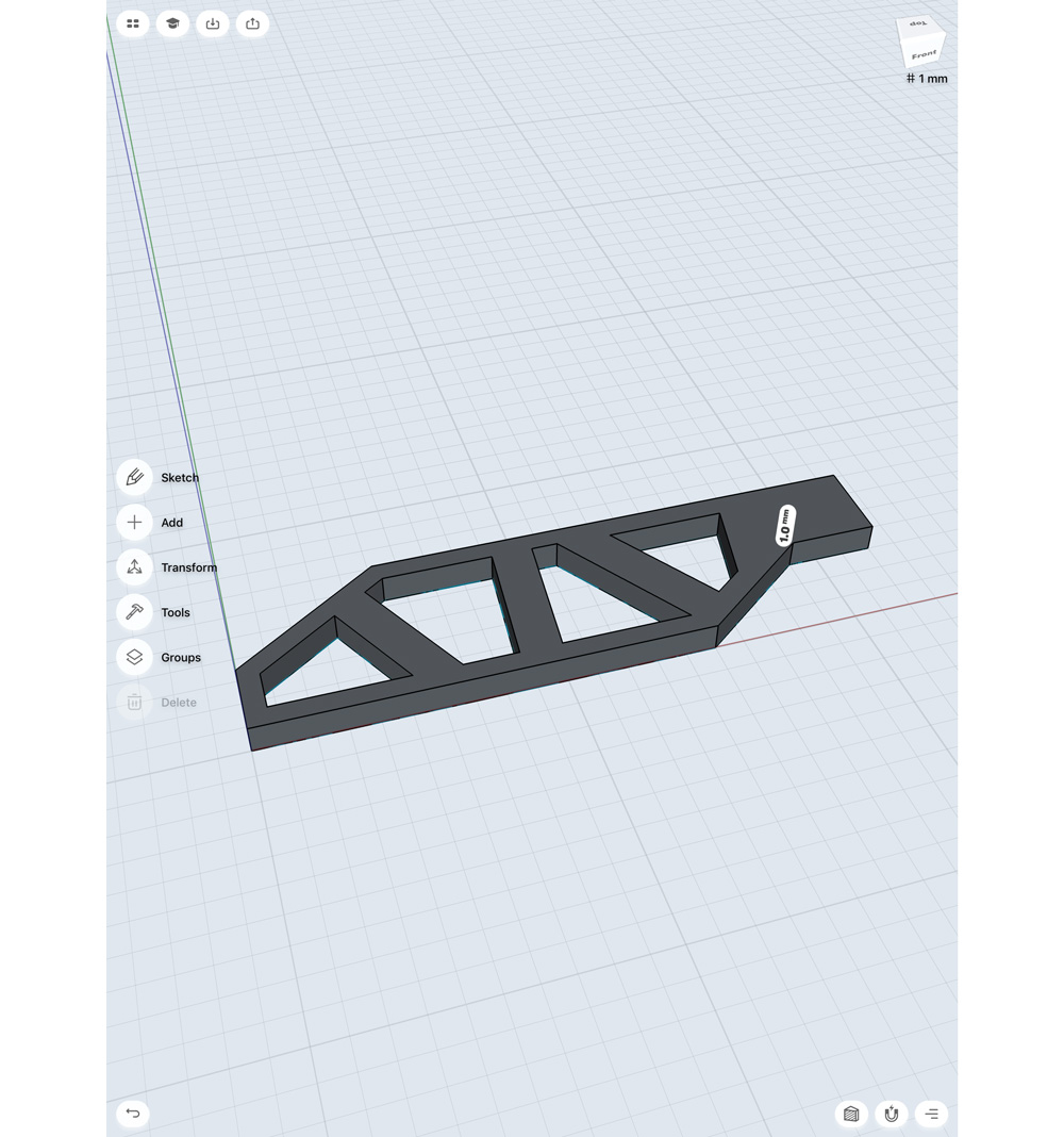
Using the pencil, select the outer ring of each section. I’m also going to select the inner polygon of my final section, so it will extrude at the same time (you’ll see why in a minute) when we drag this into a 3D shape. Using your finger, rotate the viewport to a perspective angle. You should now see a white arrow on the surface. Drag it up to create a 3D relief.
04. Use the transform tools
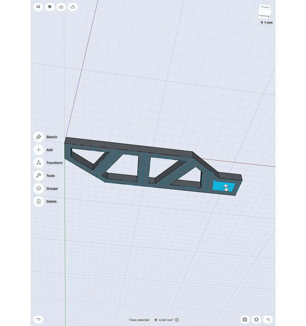
I’m now going to take that one section I didn't extrude from the base, and using the transform tools, I'm going to select my sealed shape drawing, and translate it above my 3D extrusion using the Move/Rotate/ Scale function. Then from a 3⁄4 view above my geo, I'm going to select this shape, and pull it in towards my mesh to create a subtraction. In Shapr3D, when you extrude a sealed shape outwards, it creates 3D geo, but if you extrude into an existing 3D shape, it will subtract that form.
05. Bevel the edges
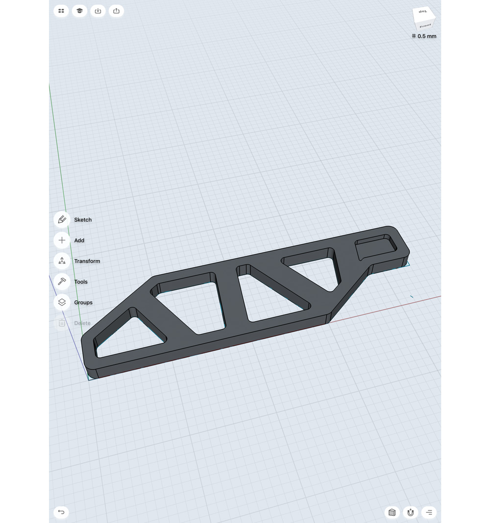
Now that we have our base shape, I'm going to bevel all the outer edges. One by one select the edges you want to bevel – as you do so the little white arrow will appear again. Pushing the arrow into the shape makes it produce a chamfer, pulling it out causes a bevel. In this case I'm going to bevel all the edges 0.6mm. I'm also going to select the edges on the inside of my mesh 0.3mm – these inner edges are closer, so I have to reduce my bevel amount.
06. Create a lip
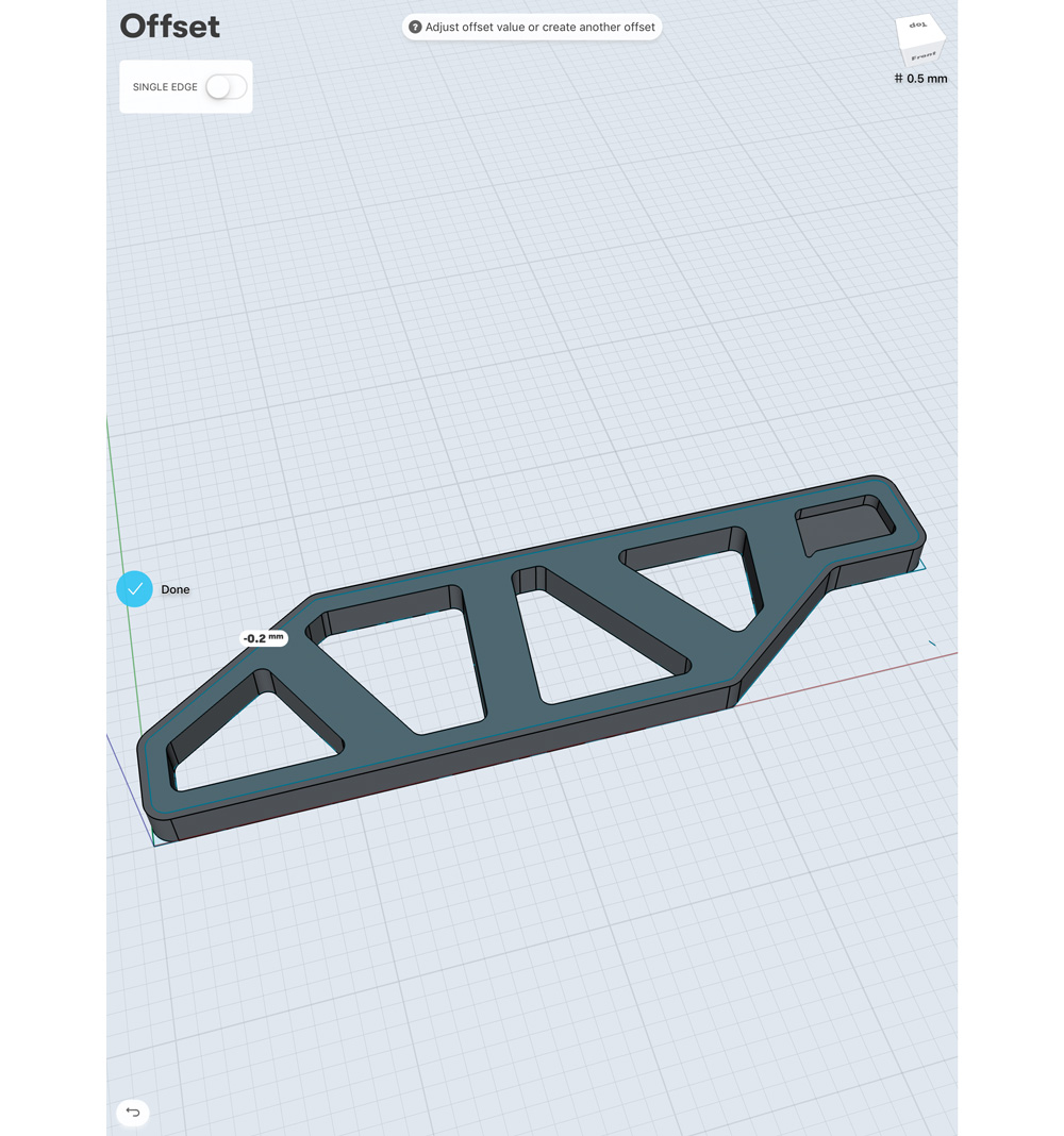
I would like to create a lip to my girder, so I'm going to have to create a new shape to subtract from my main mesh. Using the Offset tool, I can drag away from the edge of the main surface and create a shape that is 0.2mm away from my edge. This will be highlighted blue/green. When I select this shape, I can push into my mesh, subtracting an area from the centre of my geo, which will then create the lip along an edge of my shape.
07. Make screw holes
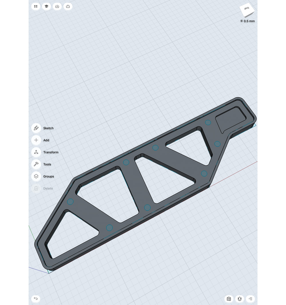
Before we wrap this shape up, I want to make some screw holes. On the top surface of the geo, I draw a circle. In this example my circle is .25mm. I'm going to duplicate my circle shape using the transform tools. Select Move/ Rotate/Scale and then highlight the circle. In the top left-hand corner, turn the Copy option on – any time you move the shape, it will now create a duplicate. You’ll need to be careful not to leave Copy on though, as any movement at all will create a duplicate.
08. Complete the shape
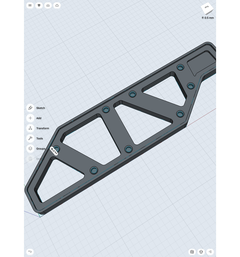
To complete this shape, I’m going to subtract the circle shape to create an indent. I will then select all the edges of my indents, and push into the shape to create a chamfer. This gives the nice look of a screw hole, and adds a level of detail that my model was previously missing.
Kitbash piece 2: Piston
09. Make a piston
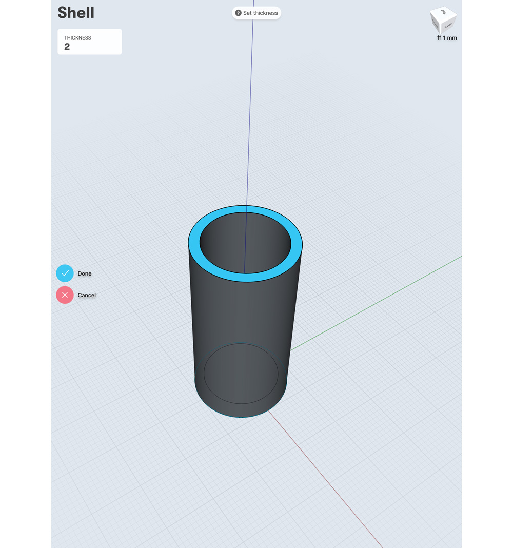
The second piece of kitbash I’m making is a piston. Start by going to the top view and drawing a circle; I’m going to set mine to 10mm. I want this shape to be hollowed out, and you can do that by selecting Shell from the tools menu. Simply select the tool, and then highlight the face you wish to hollow the shape out from (the top face). You will need to set a thickness, since our diameter is 10mm. Here I’m setting the thickness to 2mm.
10. Create a second circle
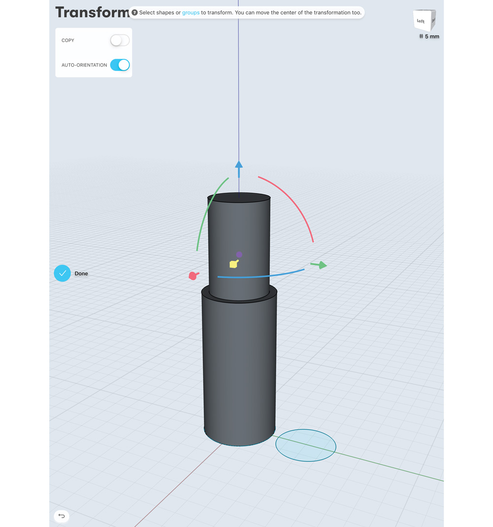
Create a second circle at 8mm diameter, and extrude it out 30mm. Double-click this geo to highlight it, and using the transform tools (Move/Rotate/Scale) move it into the newly hollowed shell of the original cylinder. Note: I have Snap To Grid turned on in the bottom right-hand side of the screen.
11. Make the central shape
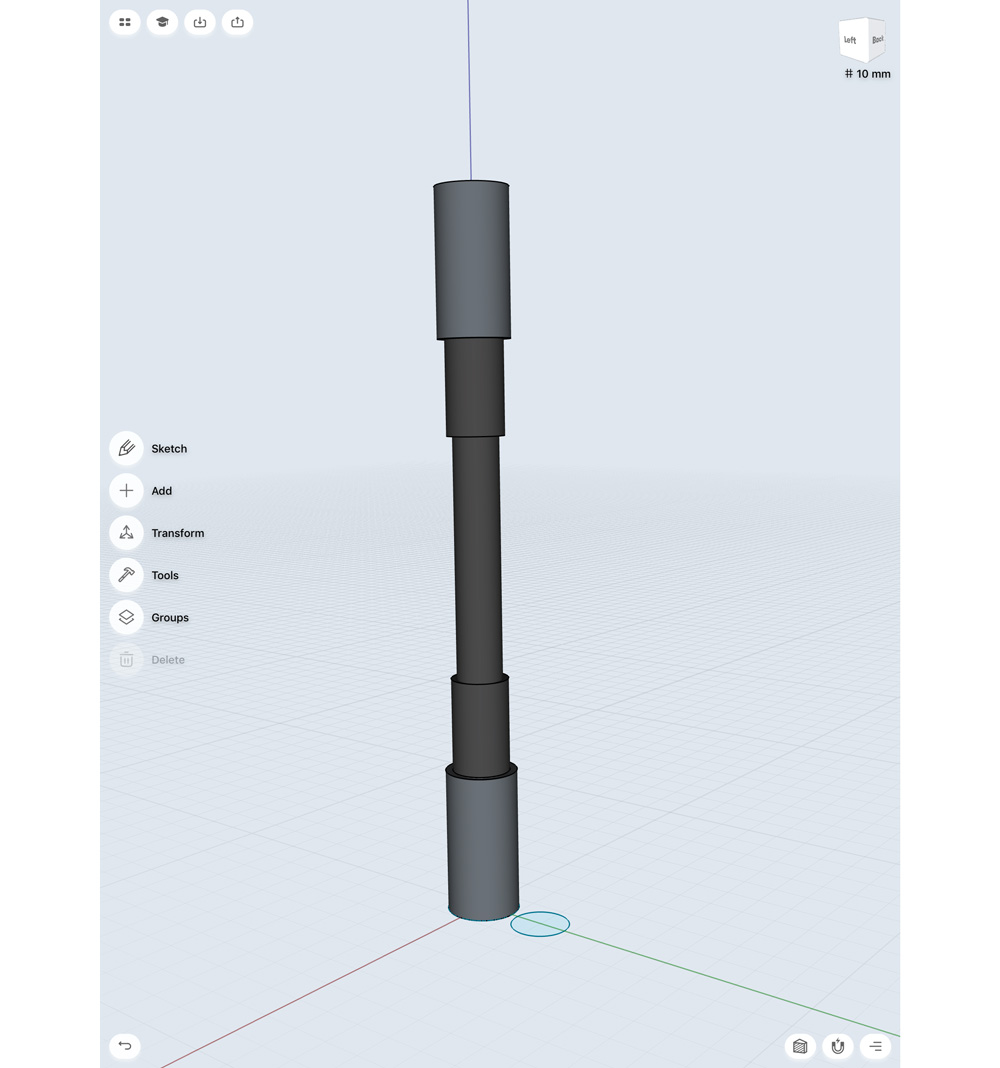
Using the Copy, Move and Mirror tools we used earlier, I'm going to duplicate and flip these pieces to make the central shape of our piston. To clarify which pieces are going to move, I will use the Colour tool (it's in the tools menu, but only available in the Pro version) to highlight the moving components with a dark grey.
12. Add a construction axis
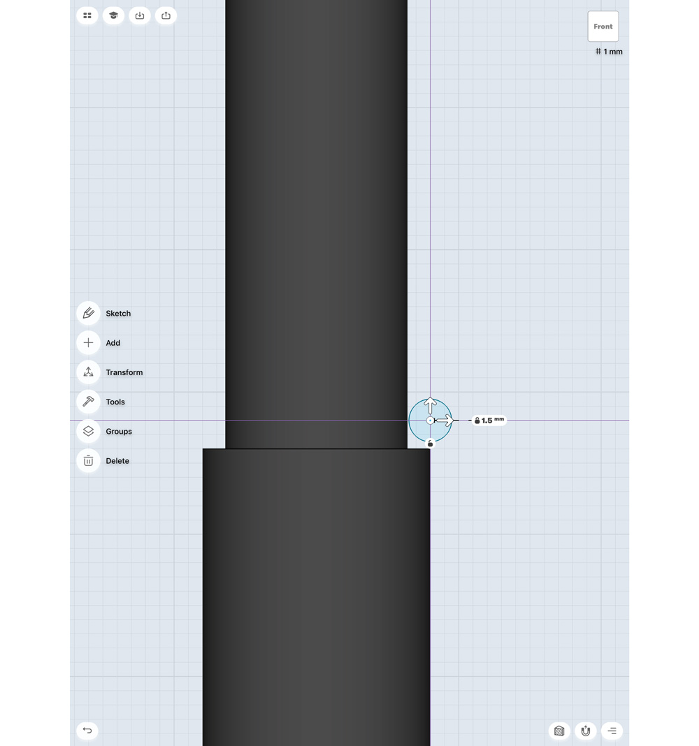
To make our spring, go to the front view and draw a small circle (in this case 1.5mm). I also want to add a construction axis to the centre of my object. I do this by selecting Add and then Construction Axis. I'm going to use the ‘through a cylinder or cone’ type – this is very easy, simply select this type in the settings, and then highlight your cylinder. It will pop blue and you should see a white dotted line running through it – this is your construction axis.
13. Create a spring
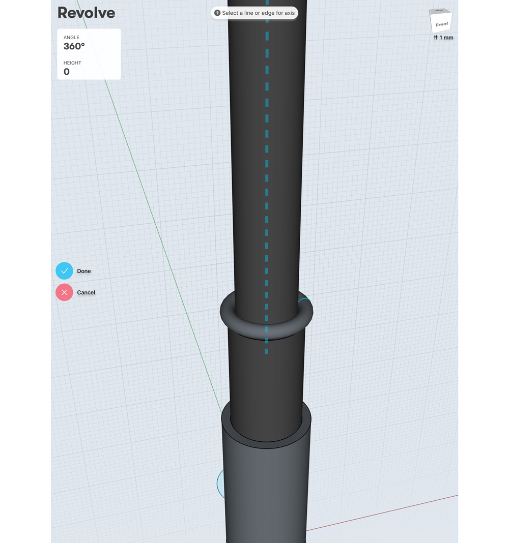
We are going to use the Revolve tool to make the spring. Select Revolve from the tools menu, now select the circle and lastly select the dotted line of the construction axis (note, you can hide geo if you’re having trouble selecting it). Immediately this should create a tubular ring around your geo. We want to offset this so it will create a spring. You can do this by changing the height value in the upper-left corner (before you complete the operation) – in this case I'm entering a height of 60mm. I will also need to increase my rotation angle, as it no longer completes just one 360, but many; I'm entering an angle of 3,000 degrees.
14. Round off the shape
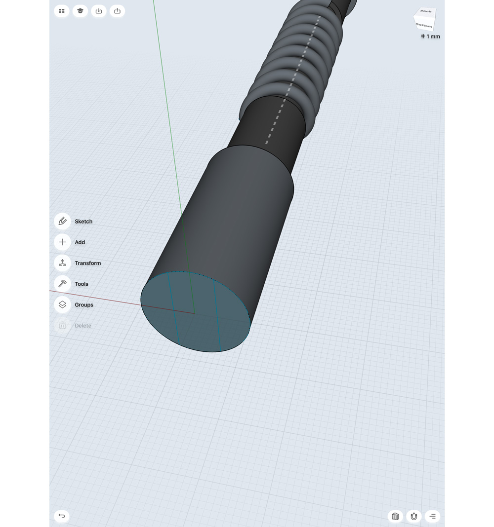
Next I want to add some loops at the end to attach our piston to whatever mechanism it ends up being a part of. Using the Sketch tool I'm going to draw two lines down the end cap. Then I'll pull the centre polygon out about 20mm. I'm now going to bevel a number of edges, the edges of the newly extracted shape, and the edges where it meets the original cap. This will round off our shape nicely.
15. Draw a circle
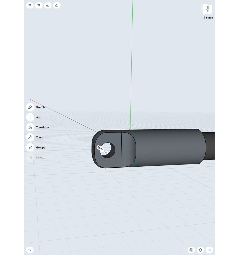
Now I'm going to draw a circle in the centre of this newly extracted tab – I have Snap To Grid on, so it should be possible to place this in the centre of my object. I'm also going to set the diameter to a nice round number (4mm). Selecting this circle shape I can push it through the object, subtracting the middle.
16. Create variations
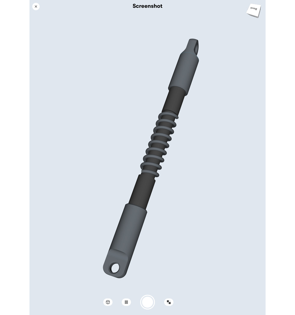
I chamfer the edges of my looped end cap, then duplicate it to the other side. I’m also going to rotate one end 90 degrees to create some variation. I could easily make a series of these pistons by duplicating the end sections and shortening them, or rotating; once you have the core pieces, it’s easy to create variations.
03. Kitbash piece 3: Balljoint
17. Start with a cylinder
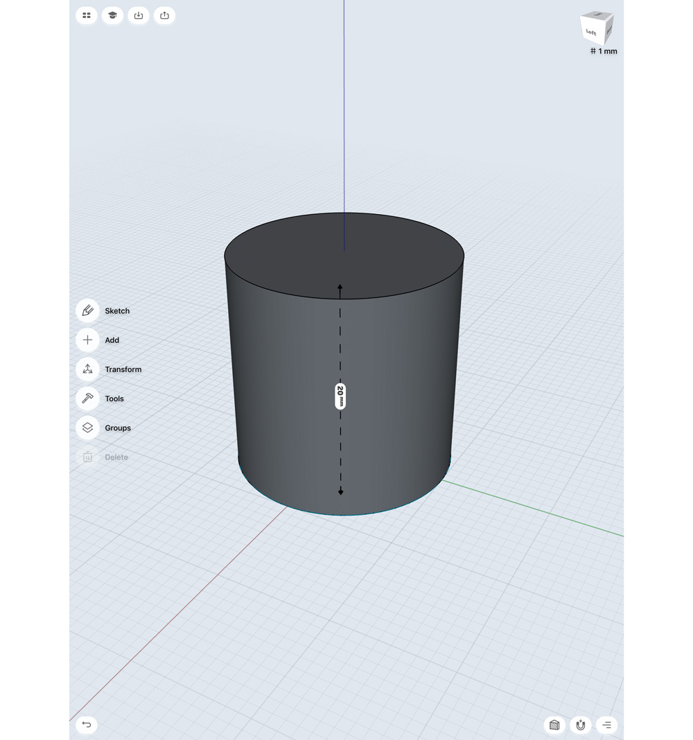
The last piece I want to make appears to be the most complex, but it’s not. The easiest way to make a ball joint is to start with a cylinder, so I'm making a 10mm diameter cylinder with a height of 20mm.
18. Bevel the cylinder
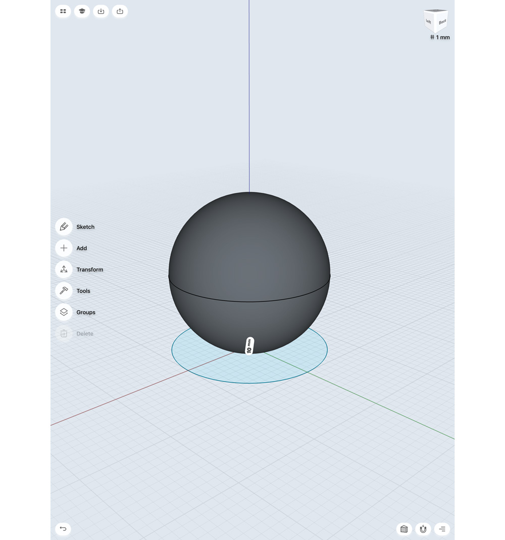
Selecting the edge of each end, I’m going to pull away from the cylinder, to bevel – I’m going to do this to the absolute maximum, it should create a perfect sphere. I’m going to leave this here, and start work on another piece now. Draw out a 20mm by 20mm square, then extrude it by about 40mm. I’m going to double-click this and select Transform > Move/Rotate/Scale and move this into position under my sphere.
19. Duplicate sphere
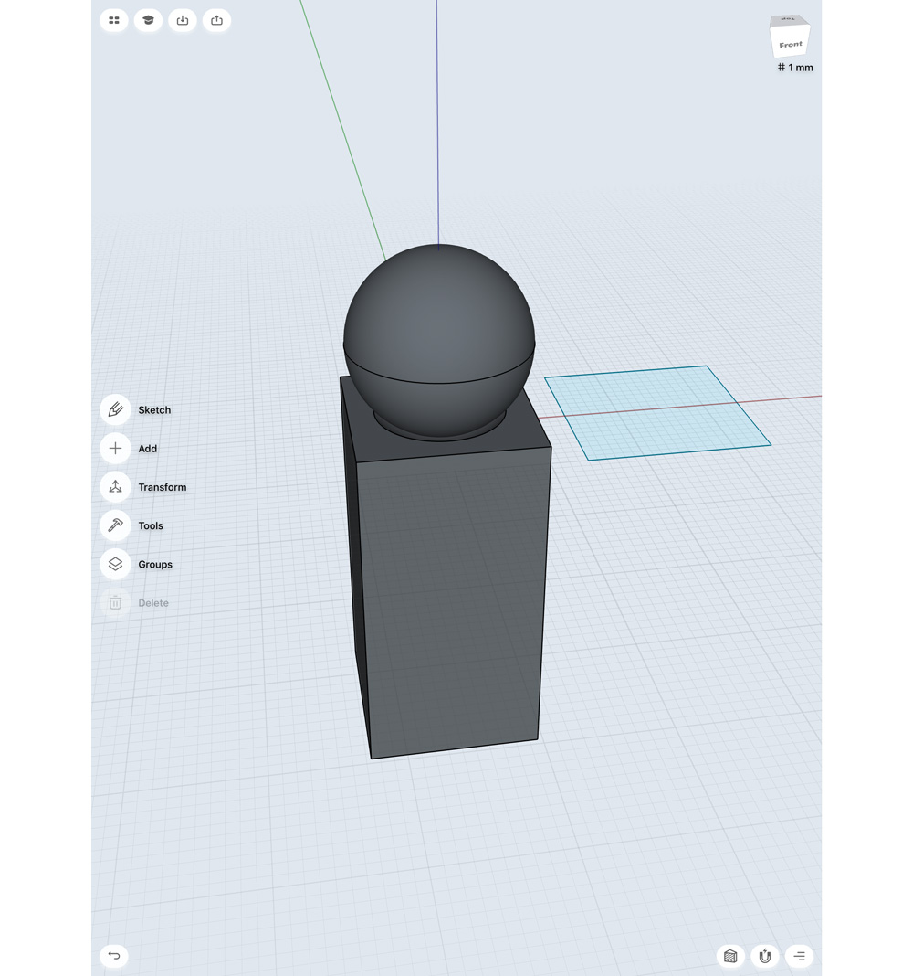
Now I want to duplicate my sphere and move it away from this construction. I’m going to need a duplicate to subtract from my cubic mesh. Once this is done, I want to move my rectangle up to intersect with my original sphere. Now I’m going to use the Subtract tool, in the tools menu. First select the object to subtract from (the rectangle) then select the object to remove (the sphere) and hit done. This should create a shape recess in my rectangle. The final step here is to move the duplicate sphere back on top.
20. Tidy up
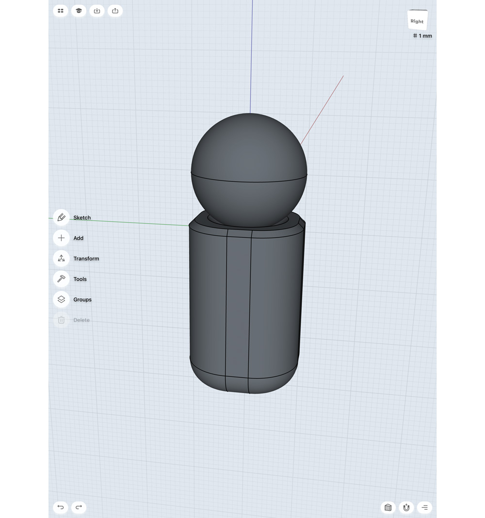
Okay let’s tidy up and make this a more interesting shape. I'm going to bevel all four edges of my rectangle about 80 per cent, to give it a really smooth look. I'm also adding a small chamfer to the top surface of the rectangle, where it meets the sphere. Lastly I'm going to bevel the lower edge, to differentiate it from the top.
21. Add vents
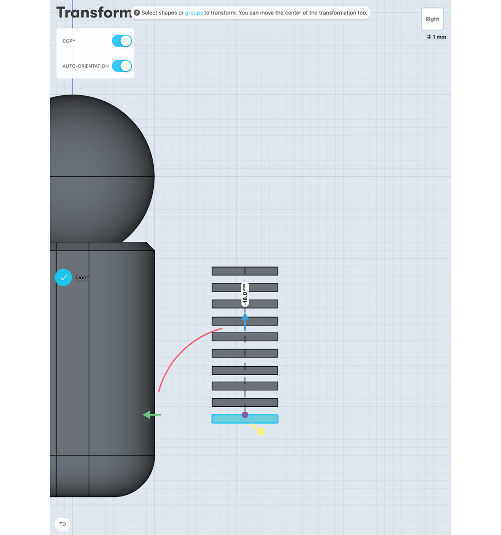
Let’s add some vents! In one of the side views, draw out a thin rectangle, and extrude it. Then using the Copy function in the Move/Rotate/Scale tool, repeat at regular intervals vertically. Use the Move tool to move all these rectangles into the centre of your object. I'm going to copy this whole group and move it into position at each corner of my object. You could also use the Mirror function to achieve this.
22. Add detail

Using the Subtract tool, we can select the object to remove, then select our vent shapes, and remove them from the main structure. Now I want to add more detail. Using the same techniques we have already gone over, I'm going to add bolt holds and detail across the surface of this object, before I repeat it to the other side.
23. Duplicate the end piece
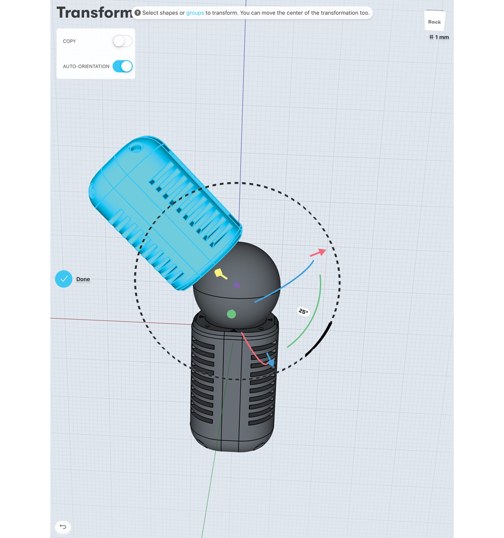
When duplicating my end piece, I centre my pivot on the sphere’s centre – then I can really see how this piece will work. From here I can rotate the other end to any angle to see how it looks. By default I’ll keep it at a straight 180-degree flip.
24. Export the file
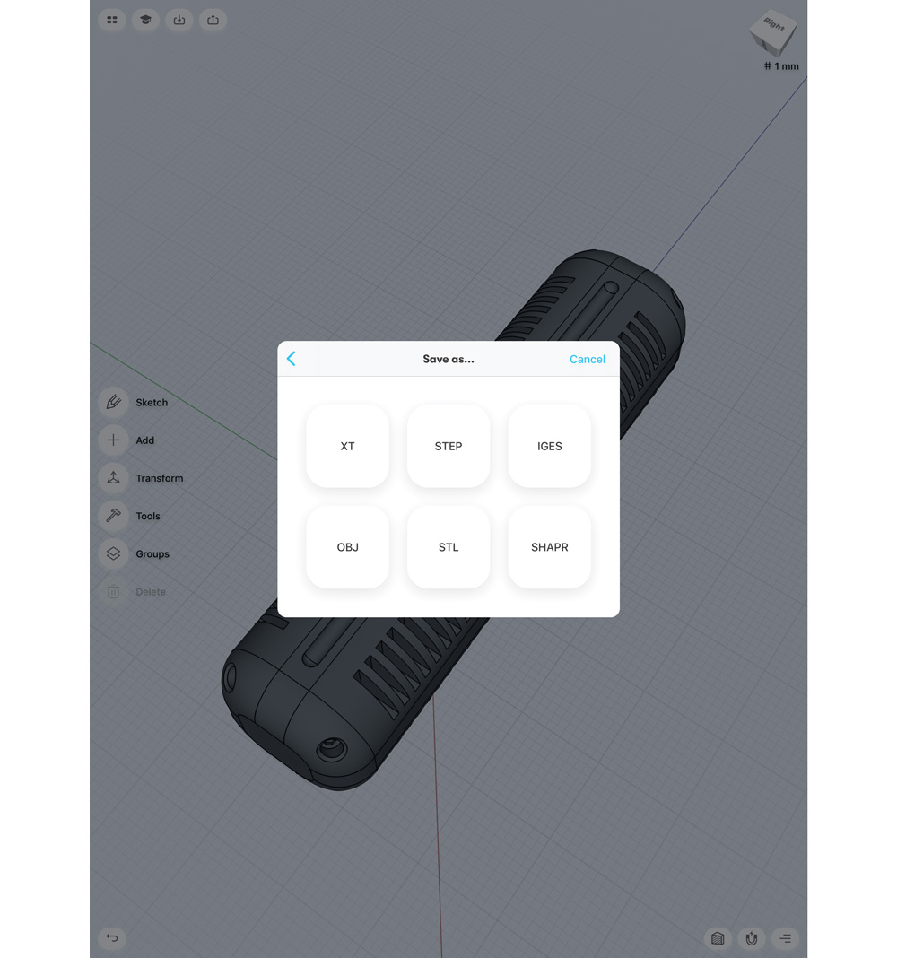
The final step is exporting. To use these pieces in a proper pipeline (and for the following tutorial next month about turning these into city building pieces), you'll need to export them. The Pro version of Shapr3D supports six formats – XT, STEP, IGES, OBJ, STL and native SHAPR. The free version only supports low-res STL. I export all my objects as OBJ to bring them into Maya as triangulated meshes. From here I can use them as kitbash components to make larger, more complex structures.
This article was originally published in issue 249 of 3D World, the world's best-selling magazine for CG artists. Buy issue 249 or subscribe to 3D World.
Read more:
- These 3D portraits are unbelievably realistic
- How to create 3D grass
- 20 Cinema 4D tutorials to sharpen your 3D skills
Get the Creative Bloq Newsletter
Daily design news, reviews, how-tos and more, as picked by the editors.

Thank you for reading 5 articles this month* Join now for unlimited access
Enjoy your first month for just £1 / $1 / €1
*Read 5 free articles per month without a subscription

Join now for unlimited access
Try first month for just £1 / $1 / €1
