10 tips for hard surface modelling
Discover the pro 3ds Max modelling tips behind this intricate steamship image.
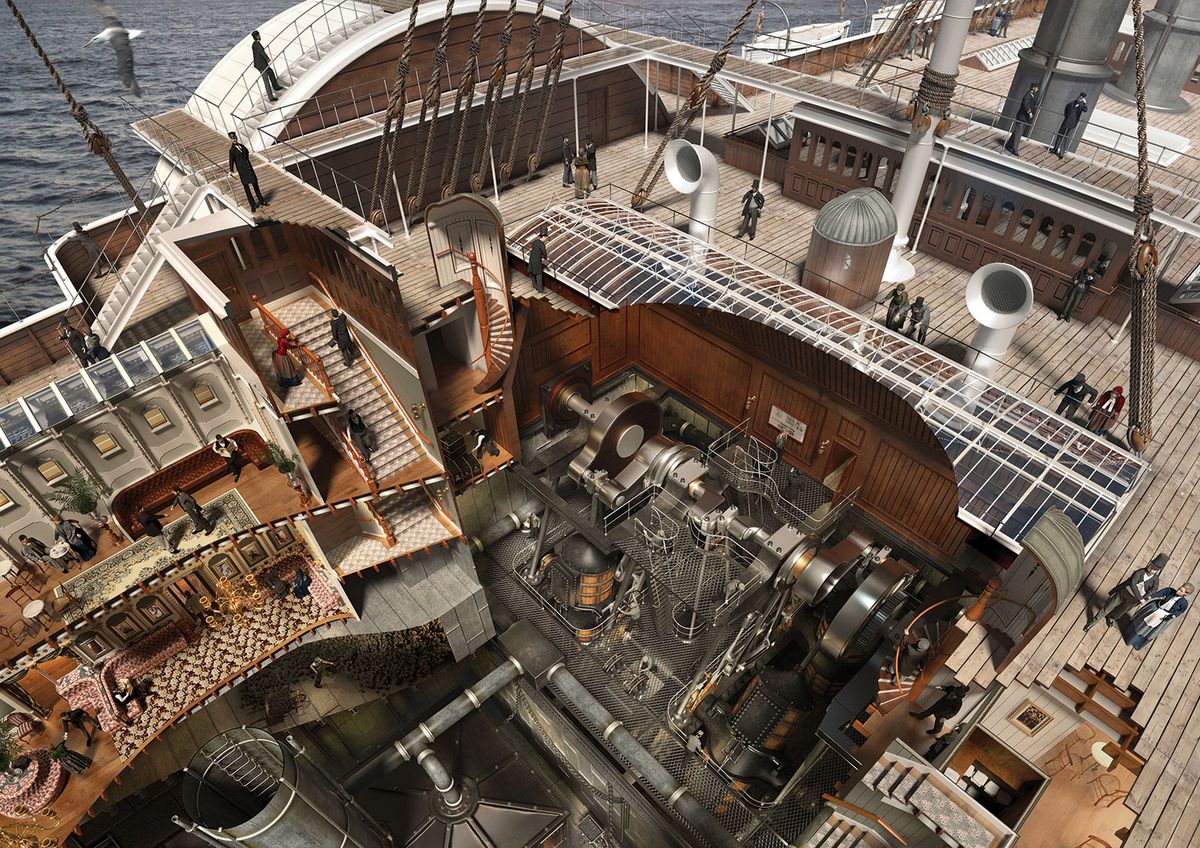
This image of Brunel's Great Eastern steamship from 1858 is on permanent display at a new £7 million museum in Bristol, which opened its doors in the spring of 2018. 'Being Brunel' is part of the National Brunel Institute and the SS Great Britain Trust.
The model in this image has been organised into multiple layers and was built primarily using 3ds Max and V-Ray. The characters were clothed with Marvellous Designer and Phoenix FD was used to generate a realistic light emitting from the ship's furnaces.
Coal piles are generated from a single object instanced many times with Particle Array, and Displacement modifiers have been used to create the gnarly rope textures. The model is lit by a blue-coloured GI environment, one VRaySun, five V-Ray Disc lights and 30 VRayIES accent lights.
For this exercise we will concentrate on the boiler room in the scene and build up one of the boiler unit 'lids'. There is of course more than one way to approach this, and with this tutorial I have broken down the process into a number of my own preferred individual steps.
Finally, I'll share how to create and easily manipulate a length of chain link into any position using a bones system.
01. Cut out a hole
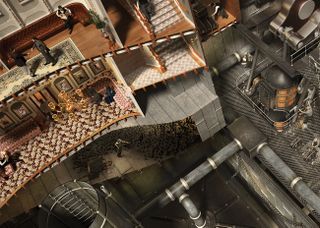
The cut-away effects in this scene were achieved by using combinations of Slice modifiers and VRayClippers.
VRayClippers can cut multiple objects, in any form and all at once, by adding them to the list inside a single 'cutter'. However, these objects will remain whole in the viewport and the cut-away section will only disappear at render time.
Get the Creative Bloq Newsletter
Daily design news, reviews, how-tos and more, as picked by the editors.
Slice is a modifier attached to individual objects but can only 'slice' in a straight line. Once applied, the sliced area will disappear from the viewport. This has the advantage of opening up the view to objects that might otherwise be hidden, making it easier to then continue modelling in that area.
02. ShapeMerge
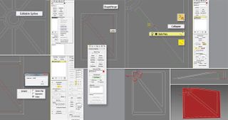
Cutting irregular polygon shapes into a simple plane can be quickly achieved using ShapeMerge. I like using AutoCAD to create a reference shape for a template. This can be imported and converted into a spline. However, shapes can also be drawn in 3ds Max using line tools and Edit Spline modifiers.
We will only need to build one quadrant of the final 'lid' object. To start, draw a rectangle with its top-left corner positioned at the centre of the template shape and its bottom-right corner to the bottom right of the shape. Detach the spline segments from the template shape that sit directly over the new rectangle and name that as 'cutter'.
Select the rectangle again and from Compound Objects select ShapeMerge. Then pick the 'cutter' as the target shape. Finally add an Edit Poly modifier to the rectangle. You have now created a flat plane object which has been divided into selectable polygon areas, the same as the template pattern.
03. Remove stranded vertices and raise rims
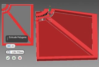
Stranded vertices need to be cleaned away from the long edges, otherwise when the top-left corner is lifted up those lengths would buckle around interrupting vertices. Groups of stranded vertices along a single edge can be grabbed in a selection and then Collapsed down to one. Using Target Weld that single vertex can then be welded to another vertex at the top or bottom of the length.
Once tidied, we can grab all the vertices and lift them up with the move tool. With the 'polygon' selection active in PolyEdit, select the rim areas in the object and click Extrude Polygons.
04. Selection tools on the Ribbon
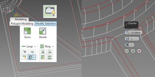
To chamfer off these newly raised rims we first need to select the appropriate edges. This can be a bit laborious when there are many small edges to pick one by one. Fortunately there are some very useful selection tools in the Ribbon menu to help with this. Here you will find a tab named Modify Selection.
Select two edges lying opposite each other on a loop, change the Dot Gap to 0 and click on Dot Loop Cylinder and the whole loop will be selected in one go. Once selected choose Chamfer in the EditPoly modifier and choose an Amount value with a single Segment.
05. Build by copying and mirroring
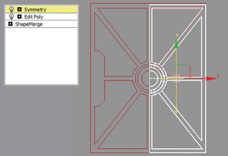
At this point in the process the single Quadrant that we have been building can now be copied and mirrored over using a Symmetry tool.
Expand the Symmetry tool down to find the mirror plane. This operates as a gizmo and can be moved and rotated until the object has assumed the correct position, while still using the line template from Tip 2 as your guide.
A second Symmetry modifier can be applied to mirror once again to complete the whole form.
06. Add detail to a polygon object
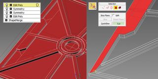
There is an additional lump along one end of our object that can be built by adding a new PolyEdit modifier. Expand the modifier down, choose Polygon and select the polygons that come within the area we wish to build in. Cut these down using Slice Plane, Slice, QuickSlice or Cut. Delete the polygons that sit inside the area, leaving an empty hole.
With edge selection activated and Shift held, drag an edge from the hole over into a new position. This will build a new polygon. Position the free edge of this correctly with the help of Snap, and seal vertices together using Collapse and/or Target Weld.
07. Round off edges
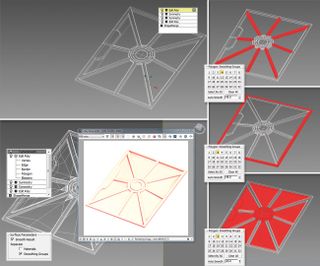
Use TurboSmooth to efficiently smooth and round off all the edges. To ensure the overall form is retained this must be done using Smoothing Groups. Select the Polygon option inside the EditPoly modifier and select groups of polygons that are to remain separate from each other. Each group of selected polygons is given a different number from the table of numbers under Polygon: Smoothing Groups.
Add a TurboSmooth modifier to the list. The object will deform out of shape until you expand and scroll down to click on Smoothing Groups under Surface Parameters. Switching up the iterations to 2 or 3 only should be fine, but be careful not to put in a very large number, or else the computer will likely hang whilst trying to calculate.
08. Add a handmade look
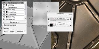
Add a VRayDisplacementMod modifier to the object and in the Texmap slot choose Composite from Standard Maps. Drag the Composite Map from the displacement modifier and drop it as an instanced copy over into an empty slot in the material editor. I have added two layers inside the Composite texture.
The first layer contains a black and white bitmap image of speckles and the second (top) layer is a Noise Map with the blend mode set to Darken. With a small displacement Amount typed in (such as 10mm) the two textures will deform the lid with dimples and dips.
09. Use a grid helper
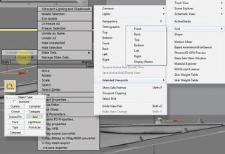
To copy objects along a line angled differently to the default X,Y,Z we can create a new UCS Grid helper. From the Helpers menu select Grid and drag the square form into a viewport. Rotate and move the Grid to the angle and position in which you would like the new UCS to operate. You have to make the UCS active by right-clicking it and selecting Activate Grid.
Finally, the viewport you wish to work in must also be activated. Click on the active view name at the top left of the viewport and from the dropdown go to Extended Viewports>Grid and then whichever view you require.
10. Build and position a simple chain link
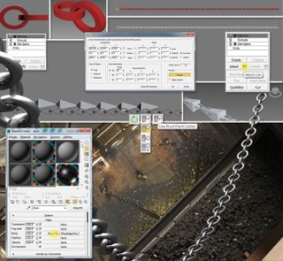
First create a single link in the chain by drawing a circle. Add a EditSpline modifier, expand down and select as a spline, then drag an Outline in the viewport. Add an extrude modifier. Drag a copy of this object and rotate it along its X axis by 90 degrees. Add an EditPoly modifier and attach the two objects together.
Under the Tools tab from the main top menu, open Array. Switch on preview and drag the X figure in the Move column so the links sit correctly. Adjust the Count figure as required, select Copy and then OK.
Select the first link in the chain, expand down EditPoly and then, beside the Attach button, select the icon named Attach List. Select all the links in the list and Attach them.
In order to manipulate and move the chain so it appears to hang, we will attach a bones system. Select the Systems button and click Bones. In the viewport click the beginning of the chain. Move along the chain, clicking at approximately every three links, then right-click to finish. You should now have a long chain of bones. Move the bone chain into position by selecting the first bone in the link, and move it around with the move and rotate tools until the whole bone system is centrally positioned over the chain. If any bones are out of place they can be individually manipulated in the same way.
Add a Skin modifier to the chain object and add all of the bones into the Bones list. Now when you move or rotate the bones around their axes, the chain will follow. The shorter the bone links are, the less deformation there will be in the chain.
Finally, drop a VRayEdgesTex in the Bump Map material slot and adjust the World width to half the extrusion depth given to the circle object in the beginning. This will round the sharp chain link edges when rendered.
This article was originally published in issue 232 of 3D World, the world's best-selling magazine for CG artists. Buy issue 232 here or subscribe to 3D World here.
Related articles:

Thank you for reading 5 articles this month* Join now for unlimited access
Enjoy your first month for just £1 / $1 / €1
*Read 5 free articles per month without a subscription

Join now for unlimited access
Try first month for just £1 / $1 / €1

