UV mapping for beginners
New to the world of UV mapping? We take you through the fundamentals of this critical 3D task.
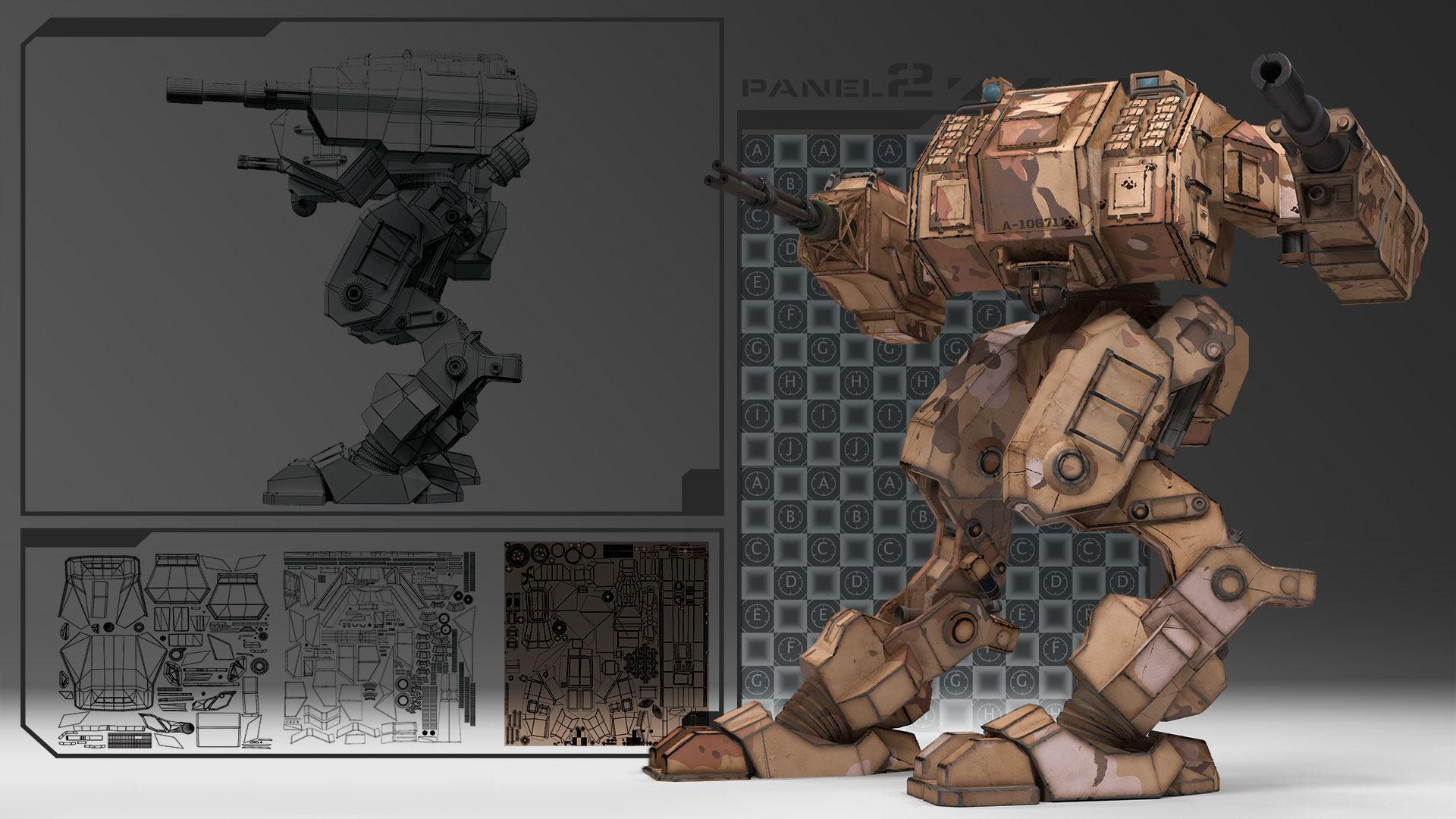
Known as the most tedious task in 3D, especially for beginners, UV mapping is also the glue that binds models, bakes and textures together. It's a crucial task, too, as a bad set of UVs and their resulting output can make even the best 3D models look awful. Whether you love or hate UVs, there's no escaping them – they are essential to understand.
Some of the most common problems that novices run into when starting out with UV mapping is finding the whole process an incomprehensible soup of terms and concepts, as well as never quite knowing where to begin, especially when working on hard-edged models.
However, if you get into the habit of doing a little prep and find a UV mapping tool you click with, it's not quite the tedium it used to be.
UV space fundamentals
The reason why a UV map is the glue between model and textures is that it's not only the flattened and mapped topology of your model, it's also the basis for your map bakes. This means you need to take your mapping into consideration as you model – bad UVs give bad bakes. You can always tweak bad curvature, height or occlusion maps in Photoshop CC at a pinch, but bad normal or similar map output can be a real pain to fix if you don't keep them in mind from the get-go.
This means the first thing you need to know about UV mapping is what UV space is. Based on a 0 to 1 grid, with 0.5 as the middle coordinates, a UV map consists of your 3D model's XYZ coordinates flattened into 2D UVW space – or tile, as it's called.
Depending on your modeller and mapper, 3D's horizontal X-axis equals U in 2D space, vertical Y equals V, and the depth coordinate Z equals W. There is no madness to the letters, only method: 2D's UVW is used solely to avoid confusion with 3D's X, Y and Z. This equalling of coordinates is – to put it simply – how 3D space translates into flattened 2D space.

You may be wondering why 2D space also has a depth coordinate. This is to make sure that no matter how you choose to map, flip or stack your UV'd bits and pieces – called islands or shells – the depth coordinate will ensure they show correctly in 3D no matter their mapping.
Get the Creative Bloq Newsletter
Daily design news, reviews, how-tos and more, as picked by the editors.
It's also vital that all your model's flattened polys need to be inside the UV tile in order to provide your baker and renderer with accurate texture information.
Some renderers and texturing applications take this a step further by also providing support for something called UDIM – U-Dimension. In simple terms, UDIM makes UV mapping and texturing easier by enabling you to create multiple UV grids for the same model by allowing you to have 10 tiles on the U-axis, and an (almost) infinite amount on the V-axis.
As with a normal UV tile, you can't have polys outside of the UDIM tiles' boundaries either, but we'll get to that later.
Pre-modelling considerations
Now you know what UV space is, we can move on to the few fundamental concepts that apply to UV mapping no matter your model, UV mapper, or whether you're using a single-tile UV map or UDIM.
First and foremost, a UV map needs to be as distortion-free as possible. This means that a texture won't look stretched or pinched when applied onto the model. It also needs to maintain scale. Textures applied onto a model should not show disproportionately to each other.
For example, the head of your mech shouldn't have a much smaller scale and details than its torso, and even worse if the arms have even larger details. You can of course work around this by using triplanar mapping when working in apps such as Substance Designer, for example, but the best thing is to get it right straight out of the gate.
As well as no distortion, a good UV map also has borders and padding. Avoid seam trouble on the tile's edges by adding a three- to four-pixel border, and get into the habit of creating enough space between your UV islands to handle edge padding and gutters to head off trouble at the pass. Even two to three pixels is often enough to avoid texture bleed and normal mapping artefacts when baking, and almost all UV mappers have functionality for this. Use it.
It also pays to keep your layout tidy and economical, with similar items arranged together, or stacked on top of each other where possible to save space. This will allow more room for the items needing finer detailing or with higher visibility; the larger the item on a UV map, the larger the texel density, meaning the more space it gets for painting and detailing.
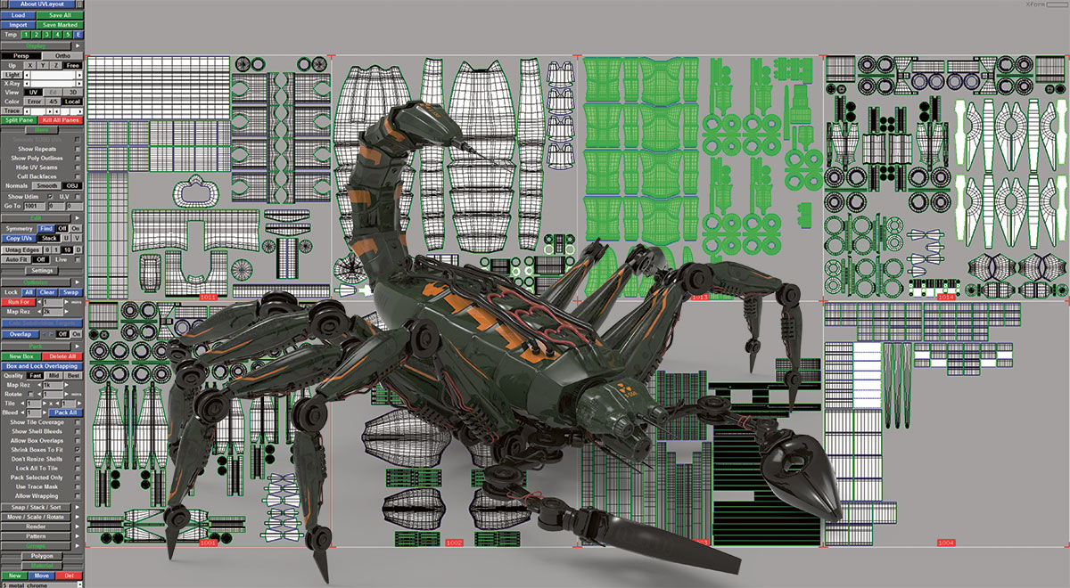
When you start modelling, make sure you build proper geometry, and keep in mind your intended end result can impact your UV map and its layout. If you're creating a game model, for example, you'll need to be very aware not only of your high-res mesh's detailing so the lower-poly mesh can hold it, but also how you cut your UV seams, as every cut means a doubled vertice count in-engine.
Neither Unreal or Unity support UDIMs natively at the time of writing, which means your map needs to fit on a single tile.
And it's never too late to start thinking about normals and smoothing groups. A lot of artists seem to think of a normal map as a glorified bump map. This is not entirely correct, as it has a few more uses than height or depth maps. In a nutshell, normals are the directional pointers for a polygon (face) or group of polygons.
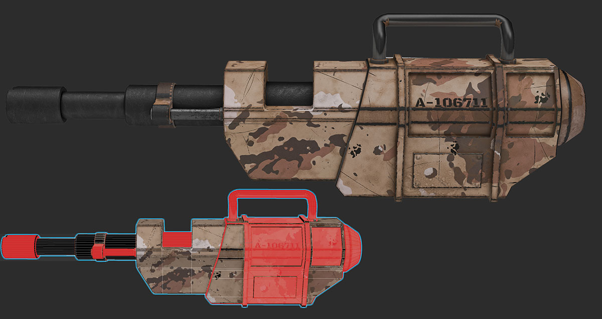
The direction they face defines the direction of smoothing, and the side or direction your materials display on. For example, if you're creating a scene inside a box, it would be natural to have the texture on the box's inner walls face inward, not outward, so you can see it.
You define this by setting the direction of your normals. Most modellers have a function that enables you to see the direction they're facing in – usually that little pointer in the middle of a polygon pointing in or outwards.
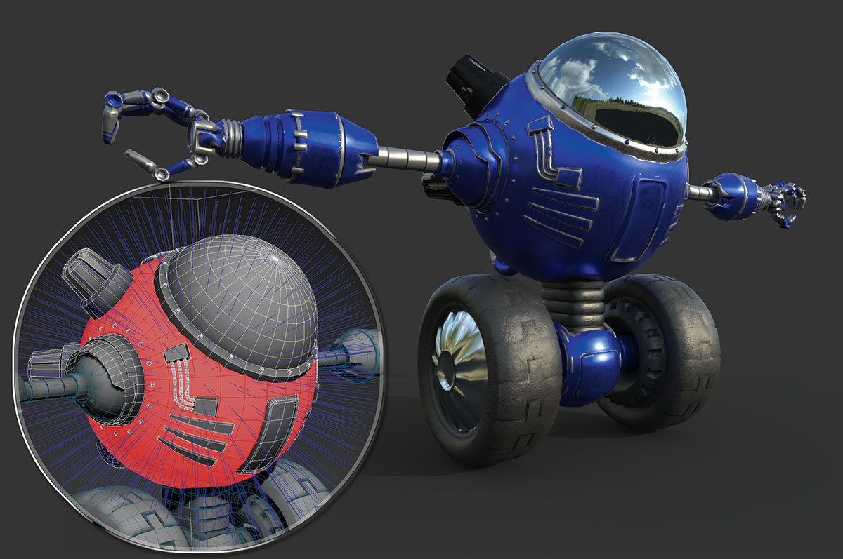
In addition to the above, and as they are items you can hand paint details on, normals also control smoothing groups. A smoothing group's function is to make your model appear smoother without adding polys to the mesh. It's a sort of pseudo-subdivision surface where if two or more polygons share an edge and are members of the same smoothing group, they will render as a smooth surface.
If not, a hard edge is created. This will render as a corner or an edge, and this edge will need to be separated when UV mapping to avoid baking artefacts. This means that even a simple thing like tidying your mesh as you go can yield baking, time saving and UV mapping benefits, as it'll steer you clear of tasks such as leftover poly clean up, too many deleted poly fixes, and tidying unclean edges, which often only become visible (and a potential clean up time sink) when you start the process of UV mapping or baking.
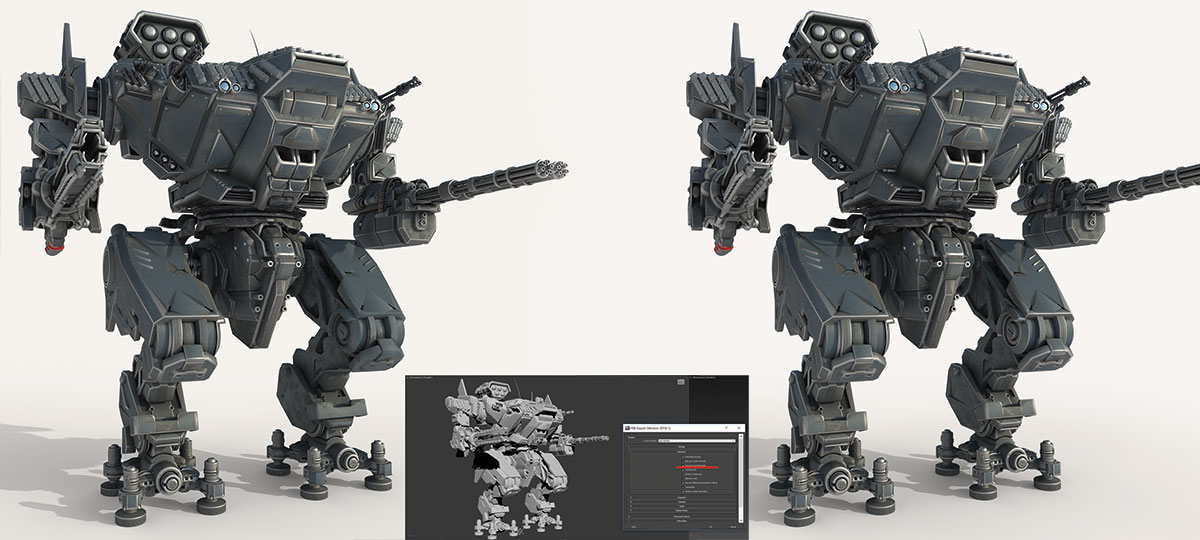
If you're UV mapping a hard-edged model, be a bit wary of flipping islands and stacking them, especially if you're mapping on a single UV tile rather than UDIM. Even though it can really speed up your workflow and save you UV mapping time to only map half of your figure before copying, flipping, welding or stacking your shells, you run the risk of ending up with weird lighting and lighting seams.
A workaround for this is to use an .fbx export with tangents and binormals checked, but it also helps to use multiple, non-flipped UV maps or sets, at the cost of load and the convenience of having everything in one map.
Hard-edged UV maps
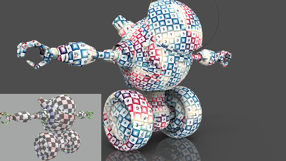
Now you know your space and are aware of some of the basic workflow considerations, it's time to start mapping for real. Bring a UV grid, elbow grease, and patience. The UV grid should have letters and shapes on it – the plain black, checkered map is not good for spotting errors like flipped polys and smaller distortions, even if your UV mapper shows stretch (blue) or pinch (red) in the model view.
The patience is because UV mapping can be time-consuming. Despite the wonders of the various auto unwrap buttons littering the UV mapping landscape, keep an eye on the auto unwrap results, as an auto unwrap function by itself has no concept of what the important and non-important areas of your texture will be.
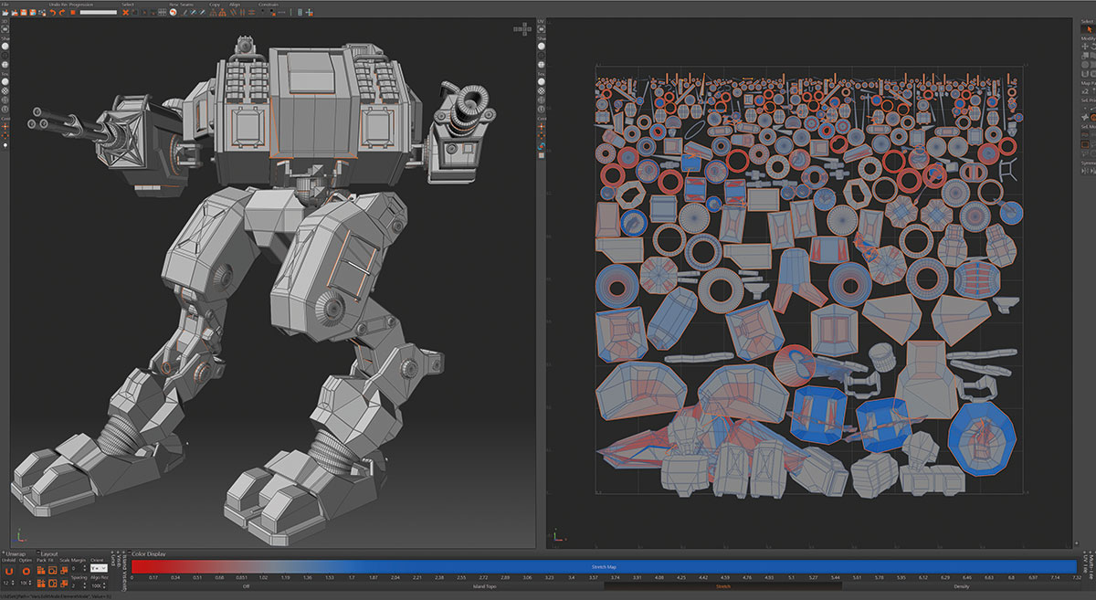
If you're absolutely stumped as to where to begin unwrapping, look at your model, and, if you haven't already, divide it into groups or material groups. Then go for the largest, or most complex items first. These areas are often the most visible and time-consuming parts of your UV map and texturing, and it's here you'll have the least leeway when it comes to time and errors.
This brings us to cutting and seams, which is where the main difference between UV mapping organic and hard-edged models lies. The reason for this is that because a mech has more edges than, say, a fantasy archer, they tend to need more seams in order to reduce distortion. But also because of normals, baking and error prevention.
In addition to high-poly details and smoothing, normals also facilitate better shading. In order to make use of this on a hard-edged model, you'll need to take some precautions when cutting your UV seams.
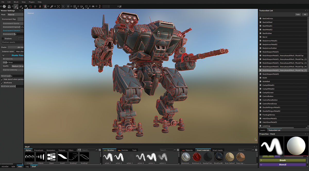
As mentioned, if you have a smoothing group or polygon ending and another one starting, a hard edge is created, and that edge is going to need to be cut and get some padding (never less than two pixels). This gives room for error reducing tangent twisting and avoids issues such as gradients, black lines or LOD issues down the normal baking line.

Take care with where you put your seams and how many you cut. A cut on a hard edge can't be avoided, but as far as the rest are concerned, try cutting your mesh in places that aren't so obvious or visible. You can also try cutting these maps approximating the way they'd be separated in real life for a good result and ease of texturing.
Staying on track
Once you've started getting into your UV mapping groove, keep an eye on your straight lines. Be careful when using the Relax function. It's a godsend for many organic maps, but can really skew your lines on a mechanical mesh if you don't use your UV mapper's pinning or constraint function properly. Test it thoroughly.
Make sure to keep your lines as straight as you can, as hard-edged models often show distortion more, and are more subject to being textured with decals and straight-lined items, which will look skewed if the UV map is skewed.
Once you're getting near the finish line, run a final check with a different UV grid and a set of generic textures, just to check everything is mapped. Once you're done, it's ready, set, bake!
This article originally appeared in 3D World, the world's best-selling magazine for CG artists. Subscribe here.
Related articles:

Thank you for reading 5 articles this month* Join now for unlimited access
Enjoy your first month for just £1 / $1 / €1
*Read 5 free articles per month without a subscription

Join now for unlimited access
Try first month for just £1 / $1 / €1
Cirstyn is a freelance CG artist and educator, with over 15 years' experience in 3D. Her clients include AMD and Daz, and she has written for 3D World magazine for a number of years. She is a certified agile (software) project manager, an avid reader and gamer.
